Working with Civil Point Symbols and Labels
Creating a user-defined Label Style
Note: All the existing Civil point attributes can be displayed in the drawing. New attributes are added with the CIVILPOINTATTRIBUTES command. The procedure for adding a new attribute is described in the Creating user-defined attributes for Civil points article.
- Open a new drawing with Civil points or Create/Import new civil points with CIVILPOINT command.
- To create a new Label Style, open the Civil Explorer panel, select Settings tab, and under Civil Points right-click on Label Styles and select Create option. You can also Edit, Copy or Delete an existing label style.
- When creating a new or editing an existing label style, the Label Style Editor dialog box will open.
- Under Info tab write the Name and Description of the new/edited label style.
- Under General tab, define general label properties including text style, label visibility, layer, orientation reference, forced insertion, plan readable, readability bias and decide if you want to flip anchors with text.
- Under Components tab, add new Text, Block, Line and/or Arrow components of the Label Style.
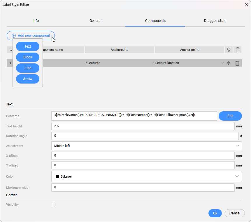
- Click Add new component button and select Text to display properties in the Civil point Label style. Define Text and Border style of the component.

To edit the text content of the label, click the Edit button to open the Text Content Editor dialog box.
- The following attributes are used in the example: Point Full Description, Point Easting, Point Northing, and Point Elevation.
- To add new property in Text Content Editor dialog box, click Add property button.
- In Add property dialog box you can choose to display Civil Point attributes in Civil Point Label style as well as properties from other Civil object (Surface, Horizontal Alignment, Vertical Alignment).Note: Toggle Use property from other objects to On and select the property you want to display in the Civil point Label style.
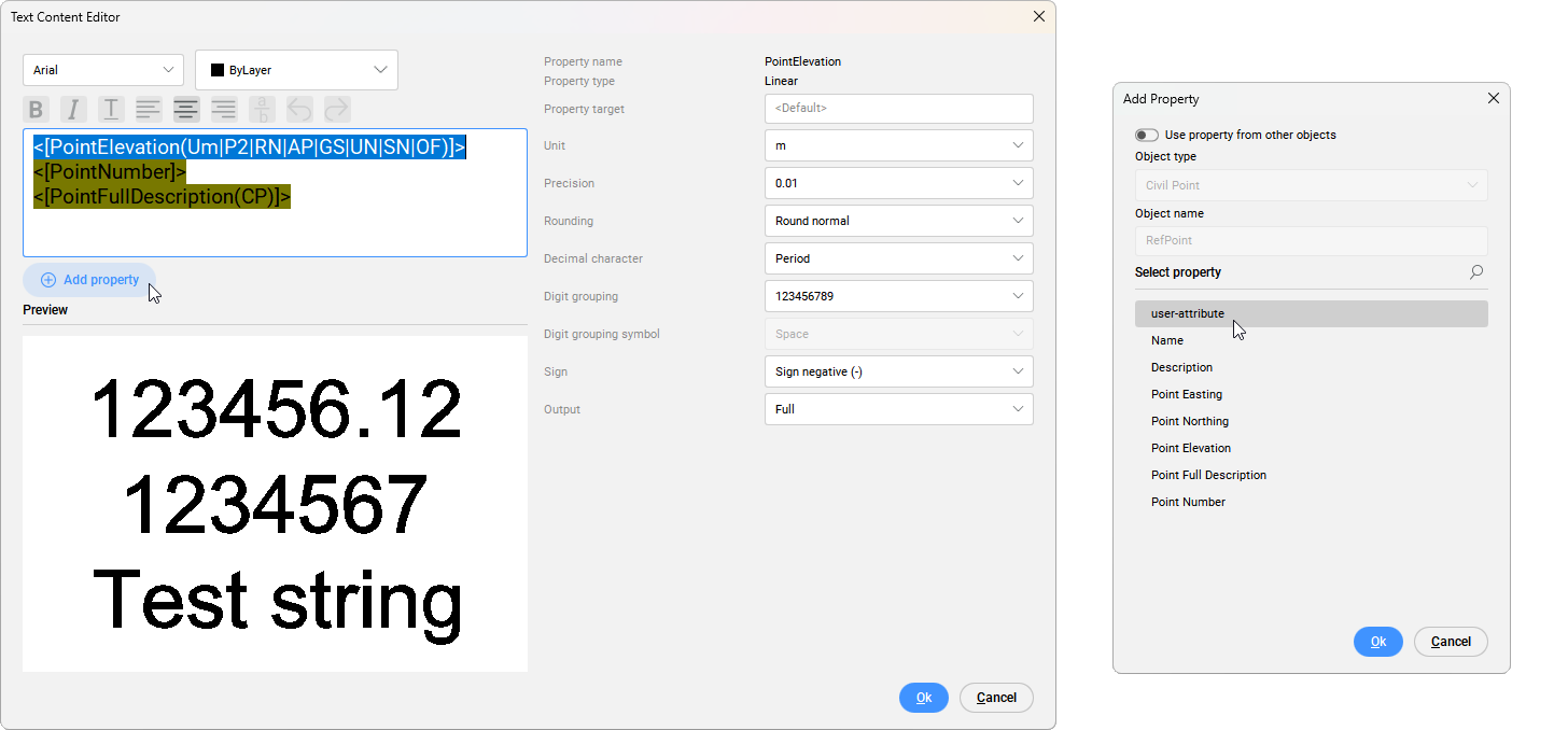
- Click the desired attribute in the text editor field and set font, color, style and position of text.
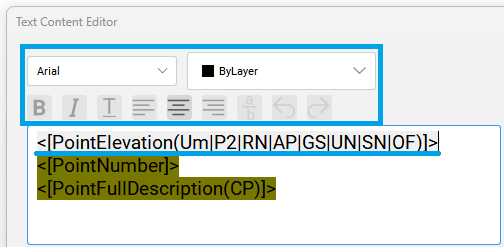
- By clicking on the individual property in the text editor field, you can specify additional settings for that property on the right side of the dialog box.
- The order of the properties can be rearranged by copying and pasting each property line in the desired place.
- Insert new text as prefix or suffix. To add a prefix, type the z = before the < character. To add a suffix, type m after the > character. For example, write z=<[PointElevation(Um|P2|RN|AP|GS|UN|SN|OF)]>m to do display points elevation.

- In Label Style Editor dialog box select Dragged state tab to define dragged state leader and dragged state components.
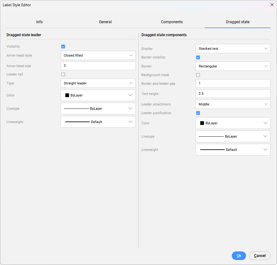
- Confirm changes by selection OK in Label Style Editor dialog box.
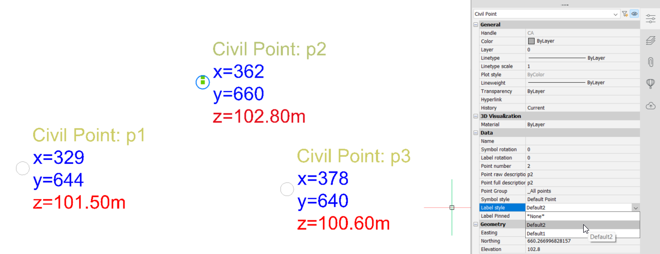
- Assign Label style to selected Civil points. Select the desired Civil points in the drawing and choose the appropriate Labels style from the drop-down list in the Properties panel.
Creating a user-defined Symbol Style
- To create a new Symbol Style, open the Civil Explorer panel, select Settings tab, and under General settings right-click on Symbol Styles and select Create option. You can also Edit, Copy or Delete an existing symbol style.
- When creating a new or editing an existing label style, the Symbol Style Editor dialog box opens.
- Under Info tab write the Name and Description of the new/edited symbol style.
- Under Symbol tab, select if symbol will be defined as Point object, Custom Symbol or as Block and define its settings.
- Point object: Uses a point object (CAD point entity) as a basis for the Symbol Style. You can define Symbol rotation (degrees) and Symbol orientation (based on object, view, or to world coordinates).
- Custom symbol: Allows you to create a symbol style from one of the custom symbols (None, Dot, Plus, X Mark, or Line). The custom symbol can be inside a circle and/or square frame. There are additional settings to define symbol size type, size, symbol rotation and orientation.
- Block: Allows you to select from a list of all point symbols (markers) that are defined by a block and present in the drawing. There are additional settings to define symbol size type (Absolute scale, Drawing scale, Fixed scale, Absolute units or Relative to screen). The process of creating and saving blocks is described in Creating blocks article. More information about editing blocks is available in Editing blocks article.
- Define symbol style Settings.
Different symbol types have different settings available.
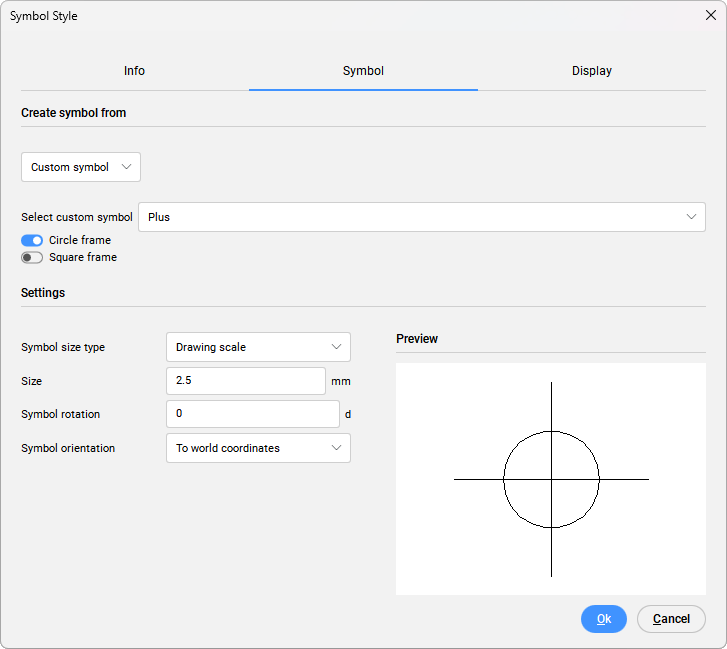
- The Symbol rotation parameter specifies the point symbol rotation angle.
- The Symbol orientation parameter controls the orientation of the symbol on user-defined coordinate system (based on Object, View, or To World Coordinates).
- The Symbol size type parameter determines how the point symbol is scaled. The following methods are available:
- Drawing units: the size of the point symbol is determined by the parameter Symbol size.
- Fixed scale: the actual dimensions of the Symbol block multiplied by the value of the Symbol size are taken.
- Absolute units: the point symbol size is specified as the product of the Symbol Size parameter and the Custom Scale parameter on the Viewport.
- Relative to screen: the size of the symbol is determined as a user-specified percentage of the drawing screen size and its maximum size.
Note: The options Symbol size type and Size are not available when starting from a Point object. Set the point style with the PDMODE variable. - Under Display tab, specify the display of your symbol component. Specify Layer settings for Plan and Model view.
- Confirm changes by clicking OK in Symbol Style dialog box.
- Assign Symbol style to selected Civil points. Select the desired Civil points in the drawing and choose the appropriate Symbol style from the drop-down list in the Civil Point Properties panel.

