Creating Corridor Template Elements
Commands
CORRIDORTEMPLATE, CORRIDORTEMPLATEELEMENT, CORRIDORTEMPLATEELEMENTEDIT
Overview
In BricsCAD®, Corridors that follow a certain 3D alignment are created using the Corridor tool.
About the Corridor Template
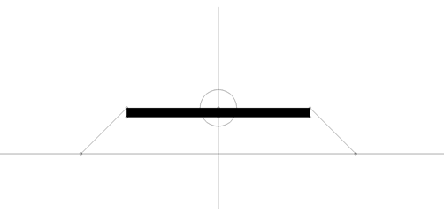
In BricsCAD®, a Corridor Template entity represents the framework to append a collection of template element objects. The CORRIDORTEMPLATE command enables you to create a corridor template entity and append one or more template elements to it.
About the Corridor Template Element
In BricsCAD®, a Corridor Template Element entity defines the geometry of a component used in a corridor section. The CORRIDORTEMPLATEELEMENT command enables you to create a corridor template element from a polyline.
About Points, Links and Shapes
A Corridor Template Element consists of the following components: points, links between points and shapes, that are created from a single or multiple links forming a polygon.
Shapes determine the geometry of the cross-sectional elements. They can be created from a single template element link or from multiple links forming a closed polygon. We assign materials to the shapes for a realistic representation of the corridor model.
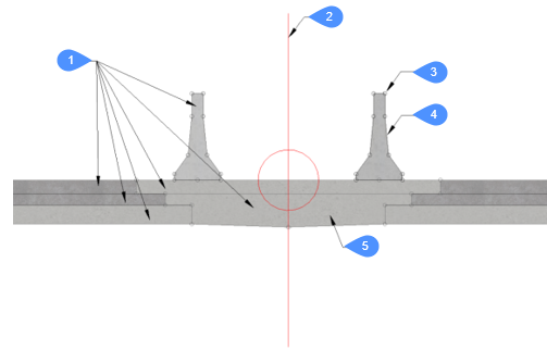
- Corridor Template Elements
- Corridor Template
- Point
- Link
- Shape with material assigned
About Corridor Targets
When the geometry of an individual corridor template element must follow a specific surface, a horizontal or a vertical object, a target is created and added to the corresponding point on the corridor template element. The following target types can be defined: Surface, Horizontal and Vertical targets.
Procedure: Step 1 - Convert Polyline to a Corridor template element
A simple polyline with 2 vertices and a (closed) polyline with several vertices can be used as an input for conversion into a Template Element. In both cases, the procedure described below should be used.
-
Draw a polyline, representing a roadway asphalt layer (in across-section view).

-
Launch the CORRIDORTEMPLATEELEMENT command.
-
Select the polyline.
-
Pick the template element base point.
-
Select the template element orientation (left, right, none).
Note:A new template element is created, consisting of two points connected with a link. The position of a second point depends on the selected point type. By default, the Delta X and Delta Y type is used. This means that the position of the second point is determined by the delta X and delta Y offset from the Origin.
The grip is placed at the specified base point of the template element.
The created template element is overlapped with the existing polyline, that can be erased now.

1. P1 -Origin (Start point)
2. P2 - End point
Step 2 - Adding points to a Corridor template element
Continue from Step 1.
- Launch the CORRIDORTEMPLATEELEMENTEDIT command.
- Select the Template Element.
- Select the option Add point in the command line.
- Specify positions for two new points, as shown on the figure below.

- Select a Corridor Template Element in a drawing and open Properties panel. Click in the Points field and click the arrow button to navigate to the point P3.
- Keep the basepoint of the point P3 set to Origin (template element basepoint), which in this example overlaps with the point P1.
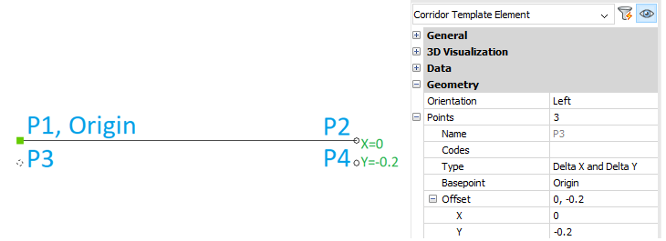
- Define the offset of the point P3 from the Origin, for example X=0, Y=-0.2.
- Navigate to the point P4 in the Corridor Template Element Properties panel.
- Set the basepoint to Point P2.
- Define the offset of the point P4 from its basepoint P2, for example X=0, Y=-0.2.
Step 3 – Editing Template Element Point Type
The value of parameter Type can be changed by selecting a different way of determining the distance from the selected Basepoint. The procedure is described below.Continue from Step 2.
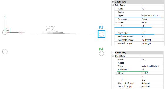
- Select the Template Element Point P2 by holding the Ctrl button, selecting the desired point, or by selecting the Corridor Template Element in a drawing and navigate to the point P2 in the Properties panel.
- Select the option Slope and Delta X from the drop-down list in the Type field.
- Type the offset distance in the X field and slope in the Slope (%) field.Note:
- The position of the point P2 is determined by the specified offset in the X direction and the slope in %.
- Point P4 moves accordingly when the position of the point P2 changes, because its Basepoint is set to P2.
Step 4 - Adding links to a Corridor template element
Continue from Step 3.
- Launch the CORRIDORTEMPLATEELEMENTEDIT command.
- Select the template element in a drawing.
- Select the option Add Link in the Command line.
- Select template element points P1 and P3 to create link between them.
- Select template element points P3 and P4 to create link between them.
- Select template element points P4 and P2 to create link between them.
- Press the Enter button to finish the command.

Step 5 – Changing Template Element Basepoint
- Select the template element in a drawing.
- Click on the Basepoint.
- Hold the Ctrl button and specify the new Template Element basepoint position in a drawing.

- Select the template element in a drawing to see a new Template Element Basepoint position.
Step 6 - Adding shape to a Corridor template element
Continue from Step 5.
- Launch the CORRIDORTEMPLATEELEMENTEDIT command.
- Select the template element in a drawing.
- Select the option Add Shape in the command line.
- Click on the links L1, L2, L3 and L4 in the written order.
- Press the Enter button to finish the command.

Step 7 - Adding an embankment line to existing Template Element
Continue from the Step 6.
- Launch the CORRIDORTEMPLATEELEMENTEDIT command.
- Select the template element in a drawing.
- Select the option Add Point in the Command line.
- Specify the new point position in a drawing

- Launch the CORRIDORTEMPLATEELEMENTEDIT command.
- Select the template element in a drawing.
- Select the option Add Link in the Command line.
- Select points P2 and P5 to create a new link.

- Select the Template element point P5 and change its Basepoint to the point P2.

- Select the Template element point P5 and change the Type parameter to Angle to Surface.

Step 8 - Adding a shape to the Embankment line
Continue from Step 7.
- Launch the CORRIDORTEMPLATEELEMENTEDIT command.
- Select the template element in a drawing.
- Select the option Add Shape in the command line.
- Select template element link L5.
- Press the Enter button to finish the command.

Step 9 - Adding the Surface target to embankment
Continue from Step 8.
- Launch the CORRIDORTEMPLATEELEMENTEDIT command.
- Select the template element in a drawing.
- Select the option Add Target in the command line.
- Enter target name: Surface-1.
- Select target type: Surface.
- Enter the target default value: -1.

1 - Template Element
2 - Surface Target
- Select the Template Element Point P5 and select Surface-1 in the Target Surface field.

Step 10 – Appending Corridor template element to a Corridor template
Continue from Step 9.
- Launch the CORRIDORTEMPLATE command.
- Pick a point in a drawing to create corridor template.
- Copy and paste an existing Template Element in the same drawing.
- Select the copied Corridor Template Element and change the Orientation parameter to Left in the Properties panel.
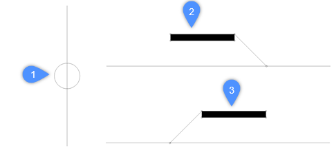
1 - Corridor Template
2 - Template Element Right orientation
3 - Template Element Left orientation
- Launch the CORRIDORTEMPLATE command.
- Select the option Add template element in the Command line.
- Select the corridor Template Element with the right orientation.
- Select the Corridor Template to append selected Template Element to it.
- Repeat steps 5 – 8 also for the Left oriented Template Element.
