AMEDGESYM command
Draws an edge symbol and attaches it to an entity.

Icon: 
Note: This command only works for drawings that contain mechanical entities. To set the environment for BricsCAD Mechanical drawings, see the Overview of 2D Mechanical Drawings commands article.
Method
Select the object to attach the edge symbol to and specify the points for its location.
After creating the edge symbol with the AMEDGESYM command, its properties can be configured in the Properties panel:
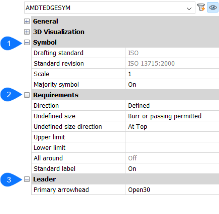
- Symbol
-
- Drafting standard
- Displays the drafting standard.
- Standard revision
- Displays the standard revision.
- Scale
- Sets the note scale.
- Majority symbol
- Chooses to display or to not display the majority symbol.
- Requirements
- Defines the edge symbol requirements.
- Direction
- Defines the position of the Undefined size sign.
- Defined
- The sign will be on a position defined by the Undefined size direction property.
- Undefined
- The sign will be on an undefined (middle) position.
- Undefined size
- Defines the edge.
- None
- Defines no requirements for the edge type. If available, upper and lower limits are displayed.
- Burr or passing permitted
- Defines the edge type as burr or passing.
- Undercut required
- Defines the edge type as undercut.
- Undefined size direction
- Defines the position of the undefined size sign.
- Upper limit
- Defines the upper value by typing it in the box or by selecting it from the drop-down list.
- Lower limit
- Defines the lower value by typing it in the box or by selecting it from the drop-down list.
- All around
- Adds the all around mark to the edge symbol.
- Standard label
- Displays the standard revision next to the symbol.
- Leader
-
- Primary arrowhead
- Sets the leader style.