AMNOTE command
Draws a leader note and attaches it to an entity.

Icon: 
Note: This command only works for drawings that contain mechanical entities. To set the environment for BricsCAD Mechanical drawings, see the Overview of 2D Mechanical Drawings commands article.
Method
Select the object to attach the leader note, specify the points for its location and write the text note. The text of the note should be formatting in the Text Formatting dialog box that opens.
After creating it, you can change the note text in the Contents field of the Properties panel.
After creating the leading note with the AMNOTE command, their properties can be configured in the Properties panel:
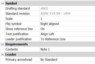
- Symbol
-
- Drafting standard
- Displays the drafting standard.
- Standard revision
- Displays the standard revision.
- Scale
- Sets the note scale.
- Flip Symbol
- Switches between Right and Left aligned text from the ending of the extension line.
- Show reference line
- Switches between show (ON) and hidden (OFF) the reference line.
- Text justification
- Specifies the location of the text regarding the extension line.
- Leader justification
- Sets the leader justification type.
- Requirements
-
- Content
- Allows you to edit the content of the note.
- Leader
-
- Primary arrowhead
- Sets the leader style.