CIVILEXPLOREROPEN command
Opens the Civil Explorer panel.

Description
Opens the Civil Explorer panel to display it in the current workspace. The Civil Explorer panel appears at the same size and location that it did before it was closed or collapsed. Like any other dockable panel, the Civil Explorer panel can be either floating, docked or stacked.
Civil Explorer is the main panel to manage and access Civil entities. Entities are arranged in a tree view and grouped by entity type.
Through this panel, you can access settings and properties of Civil entities, add new entities, and edit existing entities and their components.
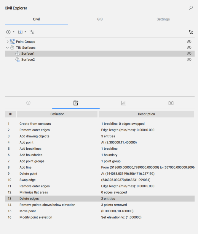
The panel is divided into two parts. The upper part displays a list of entities in a tree view. The bottom part displays additional properties, depending on the selection in the tree view.
The Civil Explorer panel is the core panel for Civil design. In the Civil Workspace, click the Civil Explorer icon in the Ribbon under the Home tab to show or hide the panel.

The Civil Explorer panel contains three tabs: Civil, GIS and Settings.
Civil Tab
If there are no Civil objects in the drawing, only the Create, Import and Attach Civil objects buttons are available on the Civil tab:
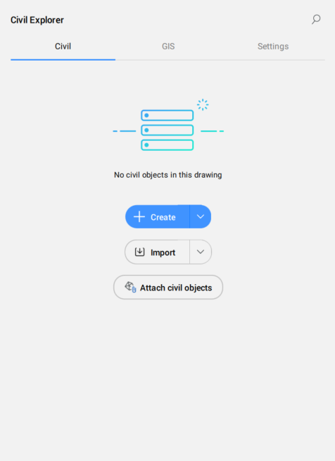
The Civil tab allows you to manage and access Civil entities in the current drawing.
- Create
- Import
- Attach Civil objects
- Pick a Civil object
- Civil object types
- Selected Civil object
- Info tab
- Definitions tab
- Statistics tab
- Visual Styles tab
- Create
- Allows you to create all types of Civil objects. Select from the drop down list the Civil object type you want to create.
- TIN Surface
- Launches the TIN command.
- Volume Surface
- Launches the TINVOLUME command.
- Grading
- Launches the GRADING command.
- Civil point
- Launches the CIVILPOINT command.
- Point Group
- Launches the CIVILPOINTGROUP command.
- String
- Launches the STRING command.
- Alignments
- Launches the ALIGNMENT command.
- Corridors
- Creates corridors.
- Corridor
- Launches the CORRIDOR command.
- Corridor Template
- Launches the CORRIDORTEMPLATE command.
- Template Element
- Launches the CORRIDORTEMPLATEELEMENT command.
- Sections
- Creates section lines and section views.
- Import
- Imports civil drawing files.
- Import Civil 3D...
- Launches the CIVIL3DIMPORT command.
- Import LandXML...
- Launches the LANDXMLIMPORT command.
- Convert Leica DWG
- Launches the LEICACONVERT command.
- Add Leica Connection
- Launches the LEICACONNECTOR command.
- Attach civil objects
- Launches the ATTACHCIVILOBJECT command.
- Pick a Civil object
- Pick a Civil object in the drawing to highlight it in the Civil Explorer panel.
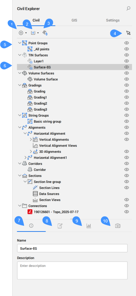
- Civil object types
- Civil objects are arranged in a tree view. At the top level, the types of objects that already exist in the drawing are listed. At the lower level, under each type of objects, the objects that already exist in the drawing are collected.
Right-click the Civil object type to open a context menu that contains the Create option, which launches specific commands to create a selected Civil object.
The right-click menu also contains a Hide option that can switch the visibility for each type of Civil object.
- Selected Civil object
- Highlights the selected Civil object in a tree-view.
-
The available edit options depend on the entity type:
- Points
- Existing individual points are not listed on the Civil tab in the Civil Explorer panel. You can create new Civil Points by clicking the Points icon in the Ribbon under the Home tab, or by launching CIVILPOINT command.
- Point Groups
- Lists all point groups created.
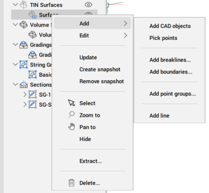
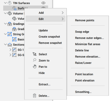
- TIN Surfaces
- Lists the TIN Surfaces existing in the drawing, including the TIN surfaces attached to the drawing with the ATTACHCIVILOBJECT command.
- Using the Civil Explorer, you can Edit existing surfaces and Add new elements to existing TIN Surfaces.Note: All the options under Add and Edit in the context menu are also available in the TIN and TINEDIT commands.
- Volume Surfaces
- Lists all Volume surfaces created.
- Gradings
- Lists all Gradings created.
- String Groups
- Lists all String groups created. The context menu contains the option Create string group.
- In addition to the common options, the context menu of a string group displays the following options:
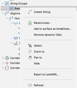
- Create String
- Launches the STRING command.
- Raise/Lower
- Allows you to raise or lower the elevation of Strings in selected String Group.
- Add to surface as breaklines
- Allows you to select the surface from the drop down menu, then opens Add Breaklines dialog box.
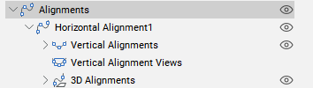
- Alignments
- Lists all Alignments created.
-
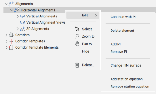
The context menu contains the Create by PI and Create by Element options, which launch the corresponding options of the ALIGNMENT command.
Right-clicking the Horizontal Alignment provides all the Edit options available in the ALIGNMENTEDIT command.
For Vertical Alignments, Vertical Alignment Views and 3D Alignments entities, the Select, Zoom to, Pan to, Hide, and Delete options are available.
- Corridors
- Lists all corridors created.
- Right-clicking the existing Corridor provides all the Edit options available in the CORRIDOREDIT command. In addition to the Edit options, the Update, Select, Zoom to, Pan to, Hide, Extract, and Delete options are available.

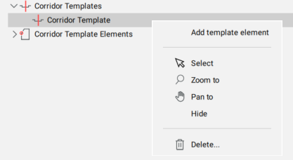
- Corridor Templates
- You can choose between Add template element, Select, Zoom to, Pan to, Hide, and Delete options.Note: The Add template element option is also available in the CORRIDORTEMPLATE command.
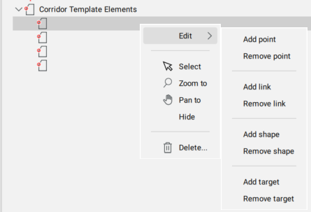
- Corridor Template Elements
- Right-clicking the Corridor Template Elements provides all the edit options available in the CORRIDORTEMPLATEELEMENTEDIT command. In addition to the Edit options, the common options, such as Select, Zoom to, Pan to, Hide, and Delete are available.
-
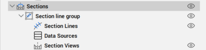
- Sections
- Lists the Section Lines and Section Views created.
-
- Connections
- Lists the connections to the Leica Infinity file.
-
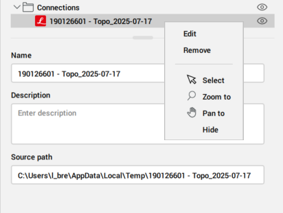
The context menu allows you to Edit or Remove the connection. The Edit option opens the Leica connector dialog box.
- Info
- Displays information about the selected Civil object (Name and Description). Both can be edited.
- Definitions
- The Definitions tab shows the components (source data) from which the TIN surface was built, the editing operations used, and the chronological order in which definitions were added.
-
- Statistics
- The Statistics tab displays statistical data for the selected TIN Surface (number of points and triangles, minimum and maximum elevations, 2D, and 3D areas) or for the Volume Surface (cut and fill volumes, 2D areas, and 3D areas).
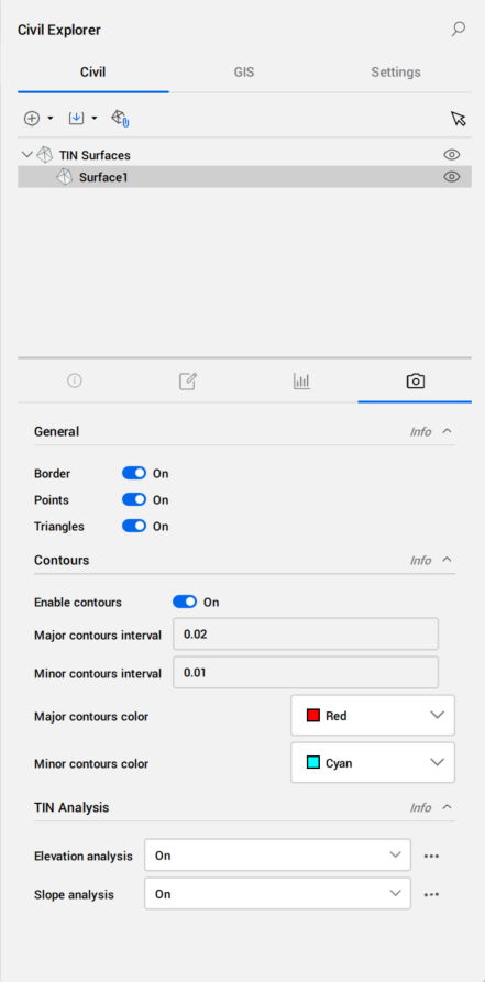
- Visual Styles
- The Visual Styles tab allows you to set the visual styles for the TIN and Volume surfaces.
- General visual style – choose which components of the TIN surface to display (Border, Points, Triangles).
- Visual style for contours.
- TIN Analysis:
- Visual style for the elevation analysis.
- Visual style for the slope analysis.
-
- TIN Analysis
- Allows you to define the parameters for TIN surface elevation and slope analysis.
- Elevation analysis
- When activated, the Elevations of the TIN surface are displayed. You can adjust the visual style of the elevations in the Elevation Analysis dialog box, which opens by clicking the Browse button (
 ).
).
- Slope analysis
- When activated, the Slopes of the TIN surface are displayed. You can adjust the visual style of the slopes in the Slope Analysis dialog box, which opens by clicking the Browse button ().
GIS Tab
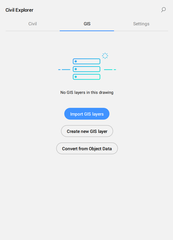
If there is no GIS layer in the drawing, there are three options on the GIS tab:
- Import GIS Layer
- Create GIS Layer
- Convert from Object Data
The GIS Tab contains a list of all the GIS layers in the drawing and helps you manage their visibility.
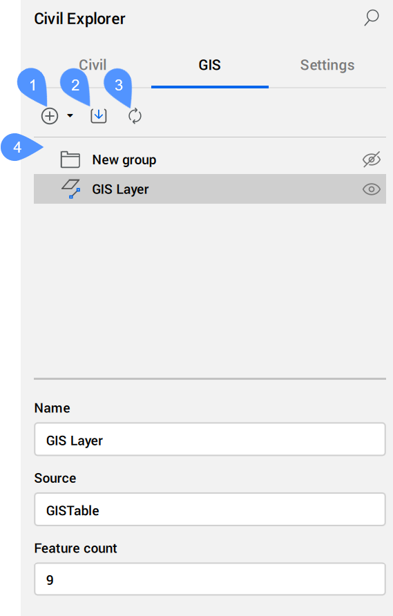
- Create
- Import GIS layers
- Convert from Object Data
- GIS tree view
- Create
- Allows you to create a New GIS layer or to create a group. Select from the drop down list the GIS type you want to create.
- Create group
- Creates a new group in the GIS tree view.
- Create GIS layer
- Opens the Create New GIS Layer dialog box.
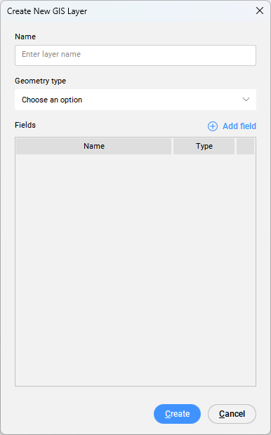
- Name
- Allows you to enter the new layer name.
- Geometry type
- Allows you choose between the following geometry types:
- Point
- Line
- Polygon
- Add Field
- Adds a new field.
When clicking the Add field button, a new field is added to the Fields list, with the default name NewField and default type String. You can edit the Name and Type fields.
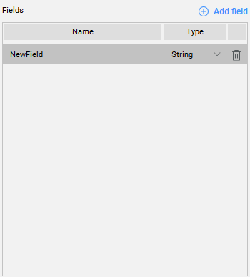
The following field Types are available:
- String
- Real
- Integer
Click the trash icon in the table to delete fields.
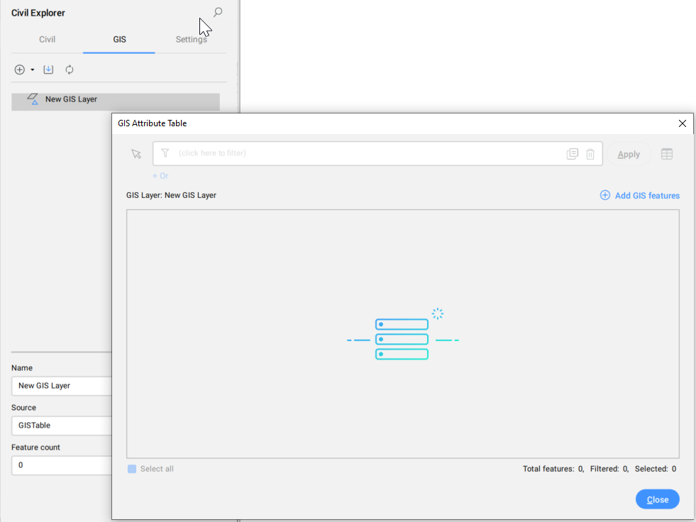
When you double-click a newly created GIS Layer for the first time, an empty GIS Attribute Table dialog box opens. To add GIS features to the GIS Layer, click the button Add GIS features. Select entities in the drawing and press Enter. The GIS Attribute table dialog box contains selected GIS features with appropriate GIS data.
- Import GIS layers
- Allows you to import ESRI SHP, GML, KML, or ESRI Geodatabase files. Check the GISIMPORT command for the detailed description of GIS Import dialog box.
- Convert from Object Data
- Converts AutoCAD® Map 3D and Autodesk® Civil 3D GIS features from the current drawing to BricsCAD GIS data.Note: The AutoCAD® Map 3D and Autodesk® Civil 3D Object Data can be viewed and edited directly in the Properties panel.
- GIS tree view
- Lists all GIS layers and groups.Note: You can rearrange groups and GIS layers by using drag and drop.
The following context menu opens when you right-click a GIS layer:
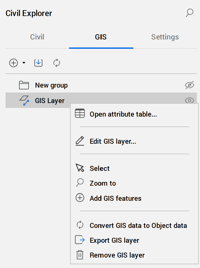
- Open attribute table...
- Opens the GIS Attributes Table dialog box.
- Edit GIS layer...
- Opens Edit GIS Layer dialog box.
- Select
- Selects the GIS Layer.
- Zoom to
- Zooms to the GIS Layer.
- Add GIS features
- Adds entities to a GIS Layer. A command prompt for selecting entities in the drawing is shown. The GIS Attributes Table dialog box opens where the new GIS features are added at the end of the table.Note: The geometry type of the GIS Layer must be Point in order to add a block to it.
- Convert GIS data to Object data
- Converts BricsCADGIS data from the current drawing to AutoCAD® MAP 3D and Autodesk® Civil 3D Object Data.
- Export GIS layer
- Exports the GIS layer.
- Remove GIS layer
- Removes the GIS layer.
The following context menu opens when you right-click a group:
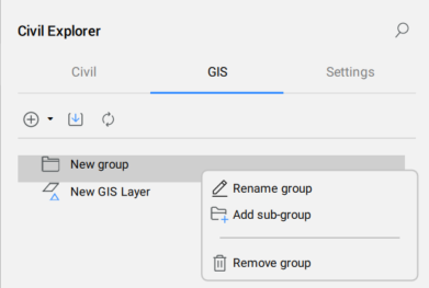
- Rename group
- Renames the group.
- Add sub-group
- Adds a sub-group.
- Remove group
- Removes the group.
Settings Tab
The Settings tab manages the civil entity styles and formats.
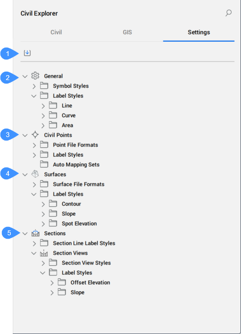
- Import Styles and Settings button
- General
- Civil Points
- Surfaces
- Sections
- Import Styles and Settings button
- Allows you to import civil label styles and civil drawing settings from other drawings. For more details, see the IMPORTSTYLESANDSETTINGS command.
- General
- Defines the general symbol and label styles for civil entities.
- Symbol styles
- Lists predefined and custom-created symbol styles. You can Create, Edit, Copy, or Delete a symbol style. Click the corresponding option from the context menu to open the Symbol Style dialog box.
- Area Label Styles
- Lists predefined and custom-created area label styles.
- Line Label Styles
- Lists predefined and custom-created line label styles.
- Curve label Styles
- Lists predefined and custom-created curve label styles.
- Civil Points
- Defines civil points file formats and label styles for civil points.
- Point File Formats
- Lists predefined and custom-created point file formats. The context menu allows you to Edit, Copy, or Delete a point file format. Click the corresponding option to open the Manage Point File Formats dialog box, or double-click the Point File Formats field.
The predefined point file formats are:
- NameENZ (comma delimited)
- NameENZ (semicolon delimited)
- NameENZ (space delimited)
- NameENZD (comma delimited)
- NameENZD (semicolon delimited)
- NameENZD (space delimited)
- NameNEZ (comma delimited)
- NameNEZ (semicolon delimited)
- NameNEZ (space delimited)
- NameNEZD (comma delimited)
- NameNEZD (semicolon delimited)
- NameNEZD (space delimited)
- PENZ (comma delimited)
- PENZ (semicolon delimited)
- PENZ (space delimited)
- PENZD (comma delimited)
- PENZD (semicolon delimited)
- PENZD (space delimited)
- PNEZ (comma delimited)
- PNEZ (semicolon delimited)
- PNEZ (space delimited)
- PNEZD (comma delimited)
- PNEZD (semicolon delimited)
- PNEZD (space delimited)
Note: The meaning of letters in file format names is:- P is Point Number
- E is Easting
- N is Northing
- Z is Elevation
- D is Raw Description
- Name is for points that contain alphanumeric values for the point number. Also, the point name supports alphanumeric values.
- Label Styles
- Lists the available label styles for Civil Points. The context menu allows you to Create, Edit, Copy, or Delete a label style. Click the corresponding option to open the Label Style Editor dialog box.
- Auto Mapping Sets
- Lists the available auto mapping sets for Civil Points. The context menu allows you to Create, Edit, Copy, Delete, or Set current an auto mapping set. Click the corresponding option to open the Auto Mapping Set dialog box.
- Surfaces
- Defines surface file formats and label styles for Contour, Slope and Spot elevation.
- Surface File Formats
- Lists predefined and custom-created surface file formats. The context menu allows you to Edit, Copy, or Delete a surface file format. Click the corresponding option to open the Manage Surface File Formats dialog box, or double-click the Surface File Formats field.
- Label styles
- Lists predefined and custom-created styles for Contour, Slope and Spot elevation. The context menu allows you to Edit, Copy, or Delete a label style. Click the corresponding option to open the Label Style Editor dialog box.
- Sections
- Defines the section line, section view, offset elevation, and slope label styles.
- Section Line Label Style
- Lists predefined and custom-created styles for section lines. The context menu allows you to Create, Edit, Copy, or Delete a label style. Click the corresponding option to open the Label Style Editor dialog box.
- Section View Styles
- Lists predefined and custom-created styles for section views. The context menu allows you to Create, Edit, Copy, or Delete a section view style. Click the corresponding option to open the Section View Style dialog box.
- Offset Elevation
- Lists predefined and custom-created styles for offset elevations. The context menu allows you to Create, Edit, Copy, or Delete a label style. Click the corresponding option to open the Label Style Editor dialog box.
- Slope
- Lists predefined and custom-created styles for slopes. The context menu allows you to Create, Edit, Copy, or Delete a label style. Click the corresponding option to open the Label Style Editor dialog box.