CUSTOMIZE command
Opens the Customize dialog box.

Icon: 
Alias: CUI
Description
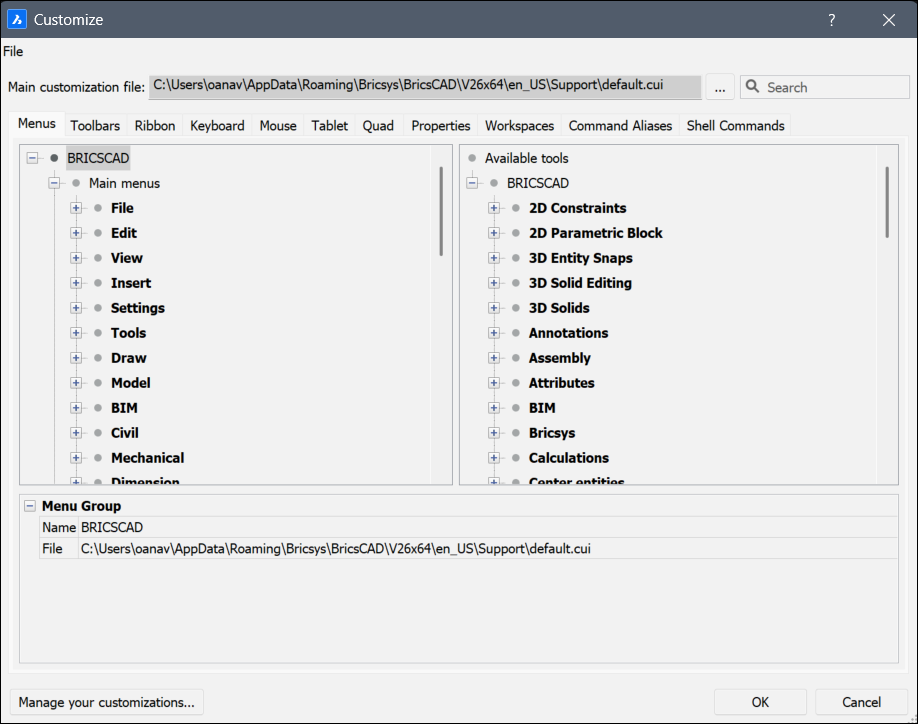
Opens the Customize dialog box.
The Customize dialog box allows you to customize the user interface of BricsCAD.
File
Click to display a context menu for selecting customization files or importing workspaces.
- Load main CUI file...
- Opens the Select main CUI file dialog box to select a customization file. See the CUILOAD command.
- Save main CUI file as...
-
Opens the Save main CUI file as dialog box to save the current main CUI file.
Note: You can save the main CUI file under a different name to copy the adapted main CUI file.
- Load Partial CUI file...
-
Opens the Choose a Customization File dialog box to open a partial CUI file.
Note: For steps to load a partial CUI file, see the Loading a partial CUI file section in the Loading and unloading CUI files article.
- Create new partial CUI file...
- Opens the Create a Customization File dialog box to create an empty CUI file.
- Import workspace(s)…
- Opens the Choose a Customization File dialog box to load one or more workspaces from another CUI file.
Main customization file
Specifies the CUI file that defines customization of the menu, toolbar, and other elements of the user interface.
- Browse
- Opens the Select main CUI file dialog box to load a different main CUI file.
- Search
- Searches the Available Tools list for command names.Tip:
- To jump to the next candidate that matches the search phrase, press the F3 key.
- To jump to the previous candidate that matches the search phrase, use the Shift+F3 keyboard shortcut.
Menus tab
Adds, edits, moves and deletes menu items.
When right clicking a menu, menu item or submenu in the Menus tab, a context menu opens. See the Options Within the Context Menu section for further explanation.
- Menu Group / Menu / Menu Item / Submenu
- Displays the options of the selected menu, submenu or menu item.
- Title
- Specifies the name that is displayed by the menu, menu item or submenu.Note: You can prefix a letter with ‘&’ to create an Alt-key shortcut. For example: &Line.
- ID
- Unique identifier for each Menu item. (The ID is assigned by BricsCAD).
- Alias
- Defines the aliases of the menu. The browse icon opens the Edit Aliases dialog box where you can edit, create or delete aliases.
- Diesel
- Specifies the Diesel code to be employed by the menu item or submenu.
- Tool ID
- Identifies the menu item or sub menu to other elements in the CUI file. (The Tool ID is assigned by BricsCAD).
- Help
- Specifies the help string displayed on the status bar.
- Command
- Specifies the command(s) or macros.
- Image
- Specifies the image to display for the menu item or submenu. The browse icon opens the Tool Image dialog box. There are five options to select an image.
Toolbars tab
Adds, moves and deletes toolbar items.
When right clicking a toolbar, tool, control, flyout or separator in the Toolbars tab, a context menu opens. See the Options Within the Context Menu section for further explanation.
- Menu Group / Toolbar / Toolbar Button
- Displays the options of the selected toolbar, toolbar button, toolbar control or toolbar flyout.
- Title
- Specifies the name that is displayed by the tooltip.
- ID
- Unique identifier for each toolbar item. (The ID is assigned by BricsCAD).
- Alias
- Defines the aliases of the selected item. The browse icon opens the Edit Aliases dialog box where you can edit, create or delete aliases.
- Position
- Specifies the position of the selected toolbar. You can choose between Floating, Top, Left, Bottom, Right.
- Default Display
- Determines whether the selected item will be added to the workspace.
- Rows
- Specifies the number of rows for an undocked toolbar.
- Xval Yval
- Specifies the distance in pixels measured from the top left corner of the screen to the toolbar. It applies to undocked toolbars.
The values are taken from the X,Y options of the toolbar as they are set in the Workspace tab.
- Diesel
- Specifies the Diesel code to be employed by the selected item.
- Tool ID
- Identifies the toolbar item to other elements in the CUI file. (The Tool ID is assigned by BricsCAD).
- Help
- Specifies the help string displayed on the toolbar.
- Command
- Specifies the command(s) or macros.
- Image
- Specifies the image to display for the toolbar button. The browse icon opens the Tool Image dialog box. There are five options to select an image.
Ribbon tab
Manages the ribbons and/or adds panels to a ribbon tab.
When right clicking a ribbon tab or panel in the Ribbon tab, a context menu opens. See the Options Within the Context Menu section for further explanation.
- Menu Group / Ribbon Tab / Ribbon Panel Reference
- Displays the options of the selected Ribbon Tab or Ribbon Panel Reference.
- ID
- Identifies the item in the CUI file. (The ID is assigned by BricsCAD).
- Collapse
- Allows you to choose if the panel will collapse automatically or if it will never collapse.
- Label
- Specifies the name that is displayed by the selected Ribbon Tab or Ribbon Panel Reference.
- Title
- Specifies the name of the selected Ribbon Tab or Ribbon Panel Reference.
- Key Tip
-
Note: Ribbon key tips are not yet implemented in BricsCAD.
- Menu Group / Ribbon Panel / Split Button / Ribbon Row Panel / Command Button / Toggle Button
- Displays the options of the selected Ribbon Panel, Split Button, Ribbon Row Panel, Command Button or Toggle Button.
- ID
- Identifies the item in the CUI file. The ID is assigned by BricsCAD.
- Label
- Specifies the name that is displayed by the selected Ribbon item.
- Title
- Specifies the name of the selected Ribbon Panel.
- Button Style
- Specifies the display mode for the selected button. You can choose between Small with text, Small without text, Large with text (vertical), Large with text (horizontal) and Large without text.Note: The icon size for the small options is 16×16 pixels, while for the large options is 32×32 pixels.
- Behavior
- Determines how the topmost button behaves when you click on it. You can choose between Drop down, Drop down with recent, Split, Split with recent, Split with recent (static text). The options determine whether the button displays the default command (the first one in the list of buttons), or the most recently used one.Note: Split buttons let you click the upper half to execute the most-recently-used command, or lower half to display the drop-list (flyout).
- List Style
-
Note: This option is not yet implemented in BricsCAD.
- Grouping
-
Note: This option is not yet implemented in BricsCAD.
- Image
- Specifies the image to display for the selected Ribbon item.
- Resize Style
-
Note: This option is not yet implemented in BricsCAD.
- Resize Priority
-
Note: This option is not yet implemented in BricsCAD.
- Justify Top
-
Note: This option is not yet implemented in BricsCAD.
- Tool ID
- Identifies the ribbon item to other elements in the CUI file. (The Tool ID is assigned by BricsCAD).
- Help
- Specifies the help string displayed on the Ribbon.
- Command
- Specifies the command(s) or macros.
Keyboard tab
Assigns different keyboard shortcuts to different commands.
When right clicking a keyboard shortcut in the Keyboard tab, a context menu opens. See the Options Within the Context Menu section for further explanation.
- Menu Group / Keyboard Shortcut
- Displays the options of the selected keyboard shortcut.
- Key
- Specifies the used keyboard shortcut.
- Tool ID
- Identifies the keyboard item to other elements in the CUI file. The Tool ID is assigned by BricsCAD.
- Help
- Specifies the help string displayed on the status bar, even though help strings are not displayed by keyboard shortcuts.
- Command
- Specifies the command(s) to associate with the keyboard shortcut.
- Image
- Specifies the image to associate with the command, even though images are not used with keyboard shortcuts.
Mouse tab
Modifies the different actions that are connected to the mouse buttons.
When right clicking a button or button group in the Mouse tab, a context menu opens. See the Options Within the Context Menu section for further explanation.
- Menu Group / Button Group / Button Item
- Displays the options of the selected button group or item.
- Alias
- Defines the aliases of the selected item. The browse icon opens the Edit Aliases dialog box where you can edit, create or delete aliases.
- Button
- Specifies the used mouse button.
- Tool ID
- Identifies the button item to other elements in the CUI file. The Tool ID is assigned by BricsCAD.
- Title
- Specifies the name that is displayed by the button item.
- Help
- Specifies the help string displayed on the status bar.
- Command
- Specifies the command(s) or macros.
- Image
- Specifies the image to display for the button item. The browse icon opens the Tool Image dialog box. There are five options to select an image.
Tablet tab
Customizes the tablet options.
When right clicking a button or button group in the Tablet tab, a context menu opens. See the Options Within the Context Menu section for further explanation.
- Menu Group / Button Group
- Displays the options of the selected button group.
- Alias
- Defines the aliases of the selected item. The browse icon opens the Edit Aliases dialog box where you can edit, create or delete aliases.
Quad tab
Adds commands to the quad tab or moves commands to other tabs.
When right clicking a quad tab or quad button in the Quad tab, a context menu opens. See the paragraph Options Within the Context Menu for further explanation.
- Menu Group / Quad Tab / Quad Button
- Displays the options of the selected quad tab or button.
- ID
- Identifies the Quad item in the CUI file. The ID is assigned by BricsCAD.
- Title
- Specifies the name that is displayed by the Quad button.
- Help
- Specifies the help string displayed on the Quad.
- Command
- Specifies the command(s) or macros related to the Quad button.
- Image
- Specifies the image to display for the Quad button. The browse icon opens the Tool Image dialog box. There are five options to select an image.
- Entity Filter
- Specifies which items will be displayed in the Quad, depending on the type of the entity.
Properties tab
Edits which properties are shown for different kinds of entities.
- Rollover
- Specifies which properties should be displayed.
Workspaces tab
Controls which menu tabs are visible in different workspaces.
When right clicking an item in the Workspace tab, a context menu opens. See the Options Within the Context Menu section for further explanation.
- Name
- Allows you to change the workspace name displayed in the workspace list, status bar and Workspace toolbar (reported by the WSCURRENT system variable).
- Display
- Determines if the workspace name is displayed by the status bar and toolbar drop lists.
- Description
- Displays a short description of the selected workspace.
- ID
- Identifies the workspace item in the CUI file. The ID is assigned by BricsCAD.
- Menu Bar
- Toggles the display state of the menu bar. See also the MENUBAR (EXCEPT OS X) system variable.
- Scrollbars
- Toggles the display of scroll bars. See also the WNDLSCRL system variable.
- Default
- Toggles whether this workspace is the default one when BricsCAD starts.
- Yes: shows this workspace when BricsCAD starts.
- No: does not show this workspace.
- Stack Type
- Determines how panels are displayed. See also the STACKPANELTYPE system variable.
- Panel Button Size
- Specifies the initial size of buttons on panels.
- Quad Button Size
- Specifies the initial size of buttons on Quad.
- Tool Button Size
- Specifies the initial size of buttons on tools.Note:
- Small: displays 16×16 icons.
- Large: displays 24×24 icons.
- Extra large: displays 32×32 icons.
- Ribbon Panel Margin
- Specifies the size of blank space at ribbon panel edges, measured in pixels. See also the RIBBONPANELMARGIN system variable.
- Toolbar Margin
- Specifies margin above and below each toolbar, measured in pixels. See also the TOOLBARMARGIN system variable.
- Tool Icon Padding
- Specifies margin between icons on each toolbar, measured in pixels.
- Delete Tool
- Specifies what to do with tool entities following the SUBTRACT command. See also the DELETETOOL system variable.
- DMAUDIT Detail Level
- Specifies messages to display. See also the DMAUDITLEVEL system variable.
- DMPUSHPULL Subtract
- Specifies whether to enable subtract mode in the DMPUSHPULL command. See also the DMPUSHPULLSUBTRACT system variable.
- Extrude Inside
- Determines how to modify the parent entity when it intersects with the extruded/revolved entity when the Auto option of the EXTRUDE and REVOLVE commands is selected. See also the EXTRUDEINSIDE system variable.
- Extrude Outside
- Determines how to modify the parent entity when it touches the extruded/revolved entity when the Auto option of the EXTRUDE and REVOLVE commands is selected. See also the EXTRUDEOUTSIDE system variable.
- Generate Associative Attributes
- Specifies whether associative attributes are generated for 3D entities. See also the GENERATEASSOCATTRS system variable.
- Generate Associative Drawings
- Specifies associativity between the 3D model and generated views (VIEWBASE) and calculated drawings (BIMSECTIONUPDATE). See also the GENERATEASSOCVIEWS system variable.
- Intersected Entities
- Determines how to modify entities that intersect with the extruded/revolved entity when the Auto option of the EXTRUDE or REVOLVE command is selected. See also the INTERSECTEDENTITIES system variable.
- Report Panel Mode
- Specifies the mode of report panel. Applicable only for commands which support it. See also the REPORTPANELMODE system variable.
- Selection Modes
- Specifies the subentities to highlight during entity selection. See also the SELECTIONMODES system variable.
- Sheet Set Manager Auto Open
- Toggles whether the Sheet Sets panel is opened automatically when a drawing from a sheet set is opened.
- Structure Tree Config
- Names the CST structure tree configuration file to use.
- Unite Surfaces
- Determines whether adjacent extruded/revolved surfaces are united or not. See also the UNITESURFACES system variable.
- Components Config
- Names the CCF components configuration file to use.
- Menu Group
- Allows you to choose from the available menu groups.
- Title
- Shows the name of the menu displayed on the menu bar.
- Diesel
- Executes Diesel code when you select the menu.
Command Aliases tab
Customize aliases and add them to different commands.
When right clicking an item in the Command Aliases tab, a context menu opens. See the Options Within the Context Menu section for further explanation.
- Alias
- Specifies the name of the alias, a command abbreviation.Note: When you click on Alias, the list of aliases and commands is ordered alphabetically according by alias.
- Command
- Specifies the command to which the alias is assigned.Note: When you click on Command, the list of aliases and commands is ordered alphabetically according by command.
- Commands
- Lists all the available commands to add an alias to.
- Add
- Opens the Add alias dialog box to add an alias.
- Edit
- Opens the Edit alias dialog box to edit the selected alias.
- Delete
- Deletes the selected alias. A warning is displayed to confirm whether or not to delete the selected item.
Shell Commands tab
Create and edit shell commands. Shell commands run programs external to BricsCAD.
When right clicking an item in the Shell Commands tab, a context menu opens. See the Options Within the Context Menu section for further explanation.
- Alias
- Specifies the name of the shell command. This is the command you enter at the ' : ' prompt.
- Shell Command
- Specifies the operating system command to execute, or program to run.
To run a program, use the Start prefix, as in Start Notepad.exe.
- Prompt
- Specifies the prompt to display in the Command line, for example: Enter file to edit:.
- Flags
- Determines how the shell command operates:
- Don’t wait: BricsCAD immediately returns to the command prompt without waiting for the application to finish.
- Minimized: the application runs minimized.
- Hidden: the application does not appear on the screen.
- Quotes: the shell command uses quotations when the command string uses spaces, such as C:\cad programs\file name.exe.
- Add
- Opens the Add shell Command dialog box.
- Edit
- Opens the Edit shell Command dialog box.
- Delete
- Deletes the selected shell command. A warning is displayed to confirm whether or not to delete the selected item.
Options Within the Context Menu
The following options appear when you right click on an item.
- Append…
- Adds the mentioned item below the last item.
- Insert…
- Adds the mentioned item above the selected item.
- Add…
- Adds the mentioned item in alphabetical order.
- Delete…
- Deletes the menu, submenu, item or separator selected item. A warning is displayed to confirm whether or not to delete the selected item.
Manage your customizations
Displays the Manage Customizations dialog box to confirm and reverse changes made to the user interface.