EXTRUDE command
Creates 3D solids or surfaces by extruding entities.

Icon: 
Alias: EXT
Description
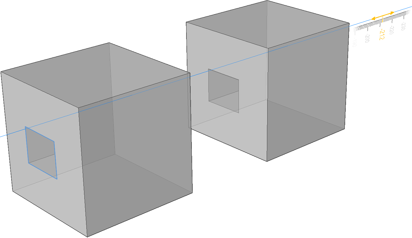
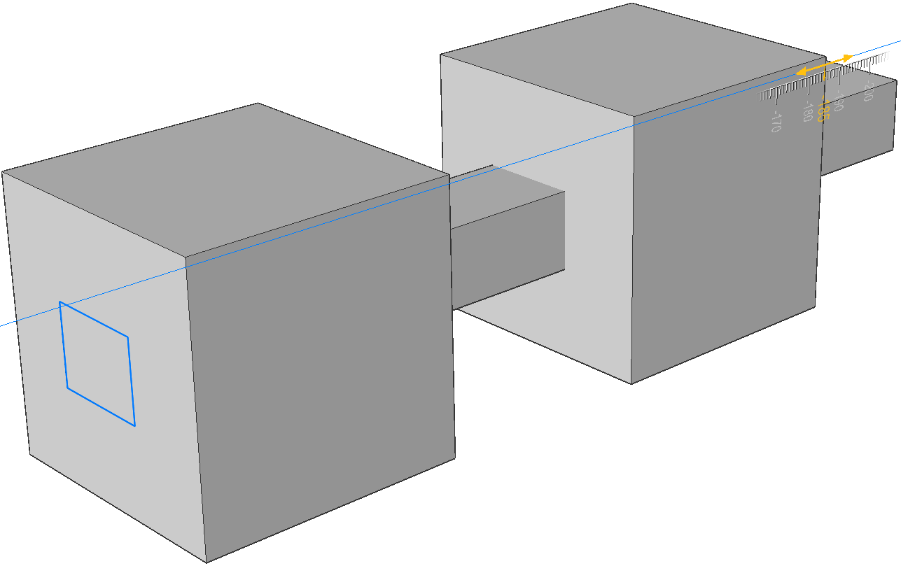
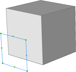
Creates 3D solids or surfaces by extruding open or closed 2D entities, faces of 3D solids, regions or closed boundaries.
Note:
- The SELECTIONPREVIEW system variable must be set to 2 or 3 to highlight faces.
- Depending on the value of the DELOBJ system variable, the source entities are either retained or deleted. If not, you are prompted whether you want the entities deleted or not.
Method
There are two methods to extrude entities:
- Create 3D solids.
- Create surfaces.
Note: You can extrude multiple profiles simultaneously.
Options within the command
- MOde
- Allows you to create either solids or surfaces.
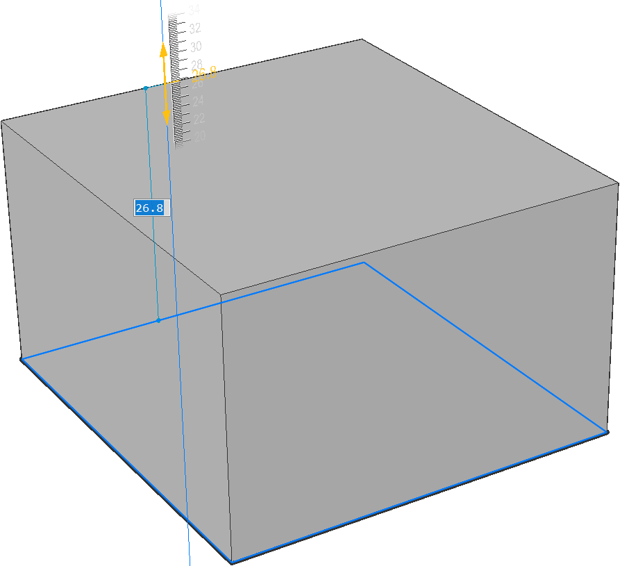
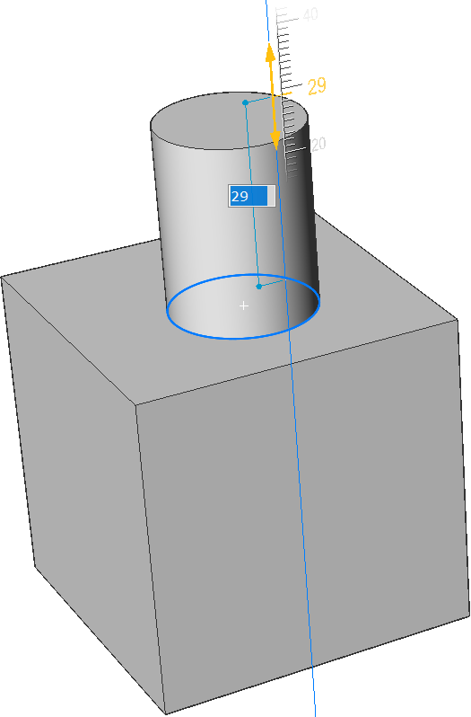
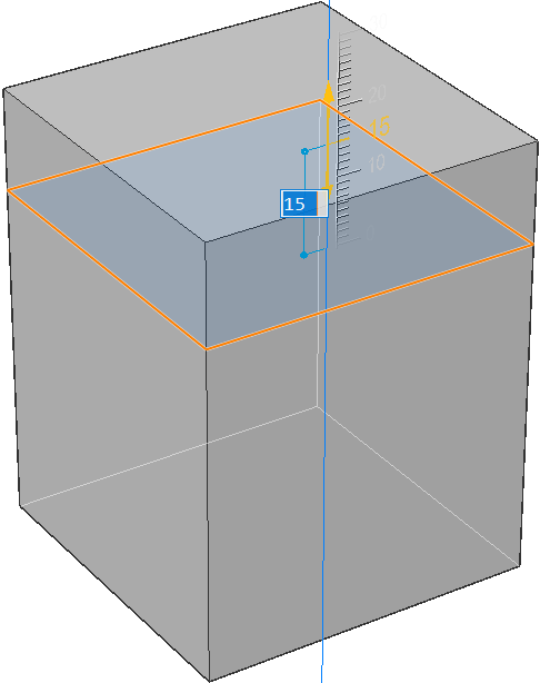
- Specify height of extrusion
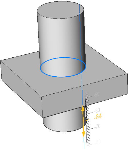
- Allows you to set a height of extrusion. The extrusion height is measured perpendicularly to the source entity.Note: You can specify the height dynamically, using the Manipulator, or typing a distance value.
- Direction
- Allows you to specify the extrusion direction.
- Path
- Specifies the extrusion height and taper by another entity. The program uses the path to determine how to extrude the source entity.Note: The path entity cannot lie in the same plane as the extrusion entity.
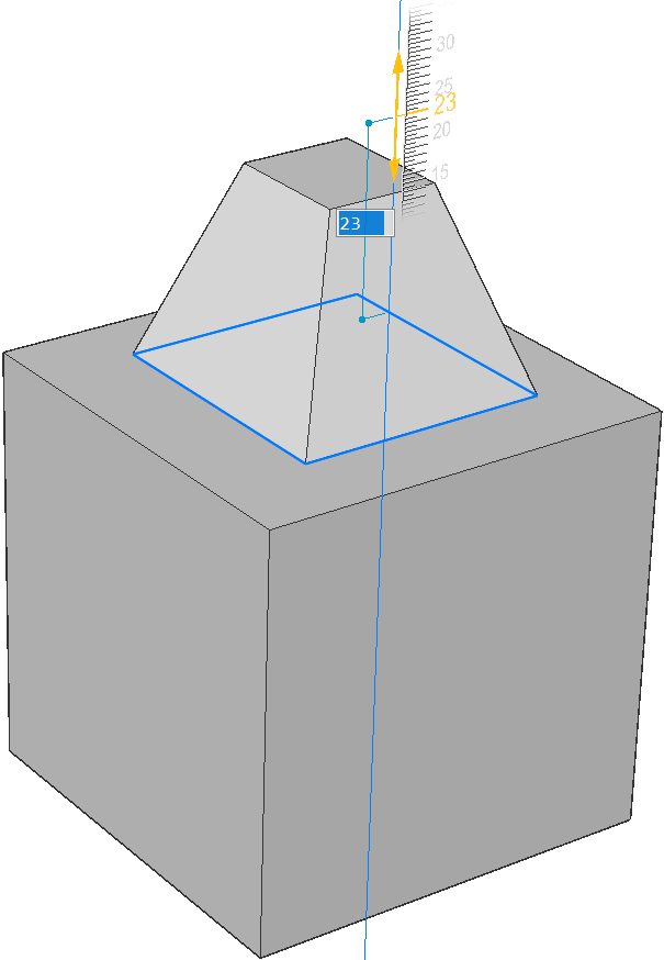
- Taper angle
- Specifies the taper angle for the extrusion. The angle is measured from the extrusion direction. A negative value tapers outwards.Note: The angle must be shallow enough so that the sloping sides do not intersect after the top of the extrusion.
- Auto
- The result depends on the extrusion direction and the value of the four Extrude mode system variables: EXTRUDEOUTSIDE, EXTRUDEINSIDE, INTERSECTEDENTITIES and UNITESURFACES.
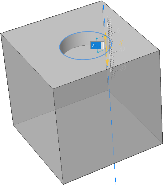
- Subtract
- The 3D solid is subtracted from each interfering existing solid.
- Create
- A new volume or surface is created, regardless of the extrusion direction.
- Unite
- The new 3D solid is unified with each interfering existing solid.
- Slice
- Cuts through solids with the extruded surface.
- Both sides
- Extrudes symmetrically in both sides.
- ALign
- Allows you to select or to define an axis.
- set Limit
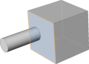
- Allows to limit the extrusion by the face of a solid.
Note: If the HOTKEYASSISTANT system variable is ON, the Hotkey Assistant widget displays. Repeatedly press the Ctrl key during the dynamic display of the extrusion to cycle the various options.


 in the ribbon.