TOLERANCE command
Opens the Geometric tolerance dialog box.

Icon: 
Description
Opens the Geometric tolerance dialog box to add tolerance symbols to the current drawing.
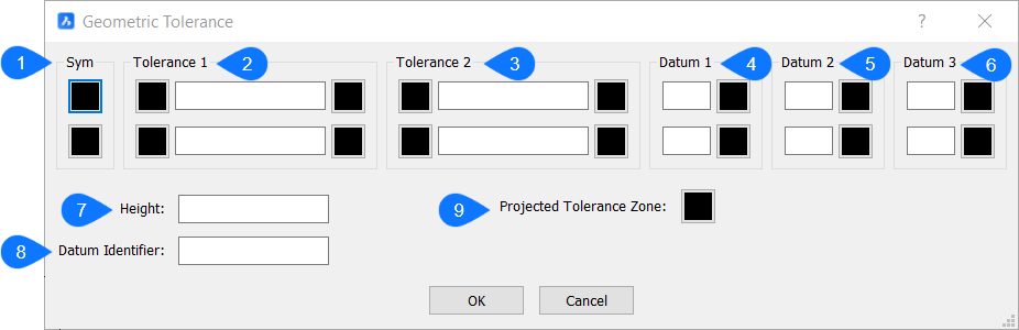
- Symbol
- Tolerance 1
- Tolerance 2
- Datum 1
- Datum 2
- Datum 3
Symbol
Specifies a tolerance symbol through the Symbol dialog box.
Tolerance 1 & 2
Specifies the tolerance specifications (diameter, value and material condition).
- Diameter
- Toggles the diameter symbol.
- Value
- Specifies the tolerance value.
- Material condition
- Specifies the material condition through the Material condition dialog box.
Datum 1, 2 & 3
Specifies the datum reference (value and material condition).
- Value
- Specifies the datum value.
- Material condition
- Specifies the material condition through the Material condition dialog box.
- Height
- Specifies the height of the tolerance symbols.
- Datum Identifier
- Specifies datum identifier, such as Datum A.
- Projected Tolerance Zone
- Toggles the projected tolerance zone symbol.
- Tolerance Symbols
-
Symbol Characteristic Type 
Position Location 
Concentricity or Coaxiality Location 
Symmetry Location 
Parallelism Orientation 
Perpendicularity Orientation 
Angularity Orientation 
Cylindricity Form 
Flatness Form 
Circularity or Roundness Form 
Straightness Form 
Profile of a surface Profile 
Profile of a line Profile 
Circular Run-out Run-out 
Total Run-out Run-out
- Material Condition Symbols
-
Symbol Definition 
At maximum material condition (MMC), a feature contains the maximum amount of material stated in the limits. 
At least material condition (LMC), a feature contains the minimum amount of material stated in the limits. 
Regardless of feature size (RFS) indicates that the feature can be any size within the stated limits.