Creates a leader by specifying a sequence of points. The leader is based on the current dimension style. Options allow you to specify the format and annotation of the leader.
Method
There is one method to begin creating a leader:
Start of leader
Options within the command
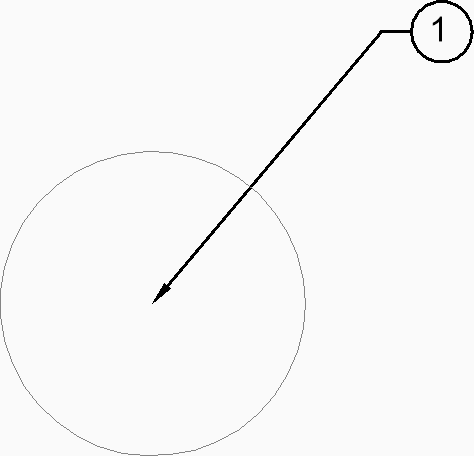
Start of leader
Allows you to begin creating a leader by specifying a start point.
Next point
Specifies the next vertex of the leader.
To point
Specifies the next vertex.
Note: You can continue adding unlimited vertices until you press Enter to access the annotation option.
Format
Specifies if the leader line includes an arrow and whether it has spline or straight segments:
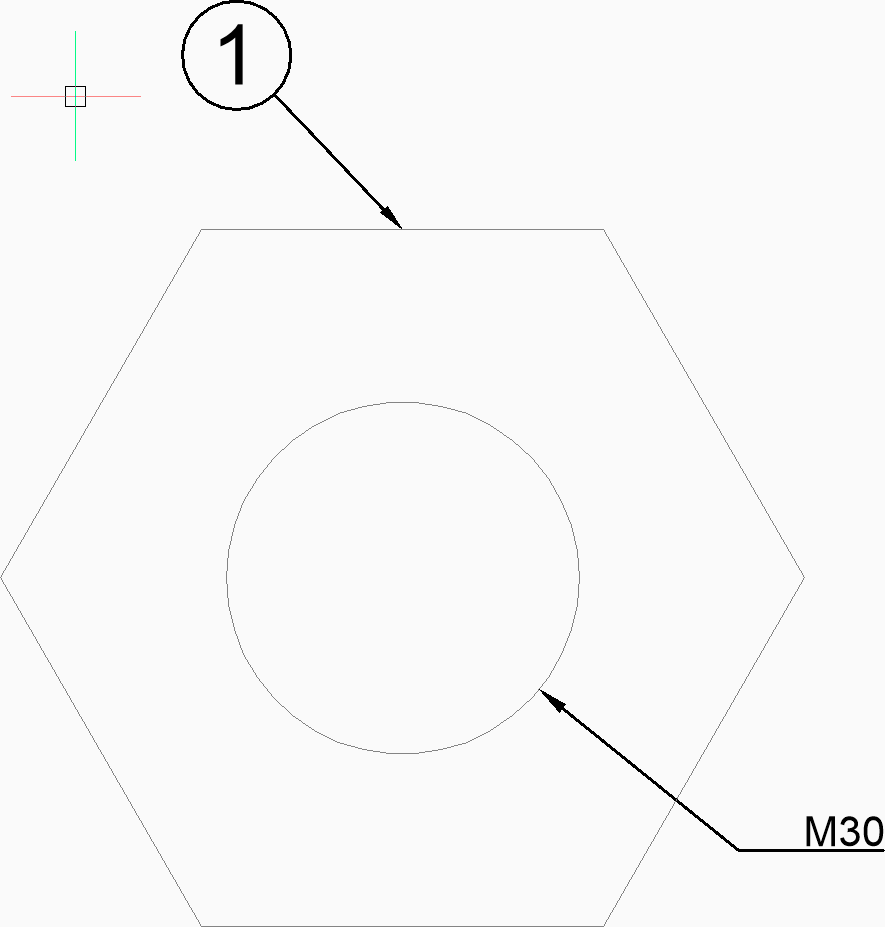
Arrow: draw the arrowhead.
None: does not draw the arrowhead.
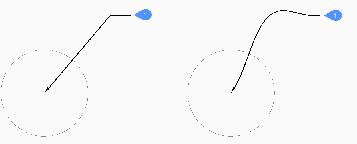
SPline: draw the leader line as a spline.
STraight: draw the leader line as straight segments.
Exit: exit the Format options.
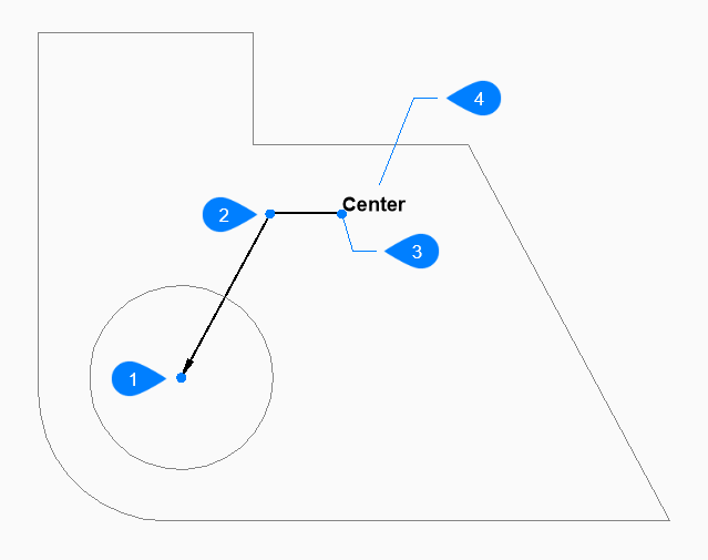
Center
Undo
Undoes the last leader line segment and continue drawing from the previous one.
Annotation
Allows you to type the lines of annotation text.
Start of leader
Next point (vertex)
To point
Annotation
options
Allows you to set the dimension text options.
Block
Specifies the name of a block in the drawing.
? to list blocks in drawing
Enter * to list the names of all block definitions in the current drawing. You can also use * as a wildcard with other characters.
Enter ~ to open the Insert Block dialog box that allows you select a DWG file to use as an annotation block.
Copy
Allows you to select an mtext, text, block reference or tolerance entity in the drawing.
None
Creates the leader line without annotations.
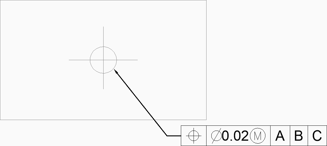
Tolerance
Specifies the tolerance using the Geometric Tolerance dialog box.
MText
Allows you to enter the annotation text using the MText editor.