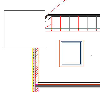
WIPEOUT command
Creates a wipeout.

Icon: 

Description
Creates a wipeout to mask parts a drawing. Options allow you to convert a polyline to a wipeout and control the display of wipeout frames.

Method
This command has 2 methods to begin creating a wipeout:
- Specify start point
- Polyline
Options within the command
- Specify start point
- Allows you to begin creating a wipeout by specifying a start point.
- Specify next point
- Specifies the next vertex of the wipeout.
You can continue adding vertices until you press Enter key to end the command.
- Polyline
- Creates a wipeout by selecting an existing closed polyline.
- Delete selected polyline?
- Allows you to choose whether to erase or retain the original polyline.
- Yes: erases the polyline.
- No: retains the polyline in addition to the wipeout.
- Frames
- Specifies whether to display wipeout frames. This is saved in the WIPEOUTFRAME system variable and applies to all wipeout entities in the drawing.
- On: displays and plot wipeout frames.
- Off: hides wipeout frames.
- Display but not plot: displays but does not plot wipeout frames.
- Undo
- Undo the last wipeout vertex and continue drawing from the previous one.
- Close
- Automatically draw a wipeout segment from the last vertex to the first one. This ends the command.

