Insert Block dialog box
Opens via: INSERT command
The Insert Block dialog box allows you to select a block definition to insert into the current drawing.
- You can insert entire DWG, DXF, or RFA files as blocks into the drawing.
- You can insert standard, parametric, or dynamic blocks.
- For block containing attributes, you are prompted to enter values in the Command line or through the Edit Attributes dialog box, depending on the value of the ATTDIA system variable.
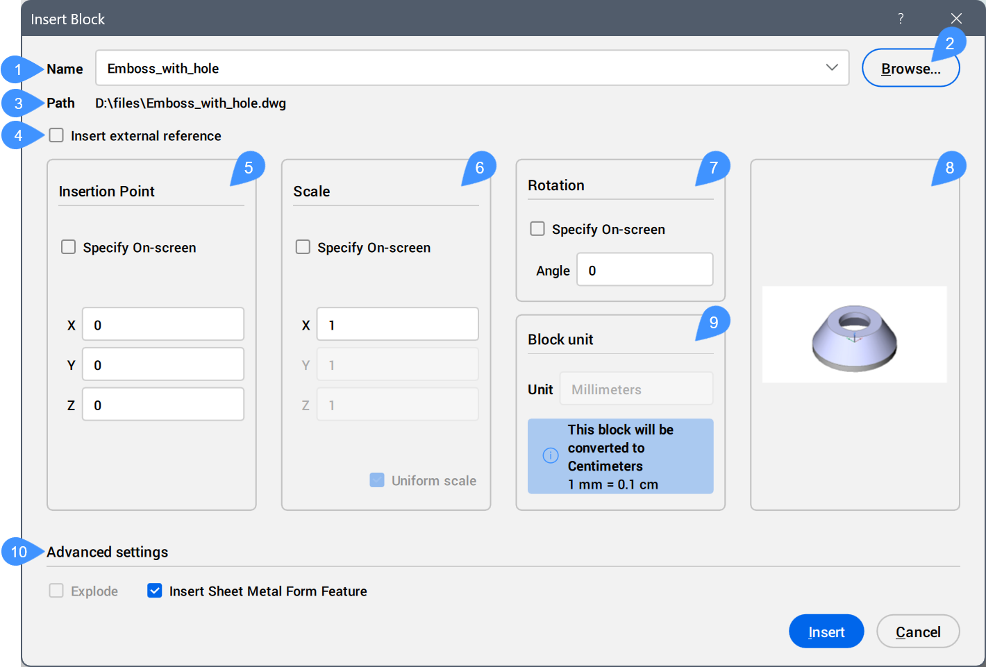
- Name
- Browse
- Path
- Insert external reference
- Insertion Point
- Scale
- Rotation
- Block preview
- Block unit
- Advanced settings
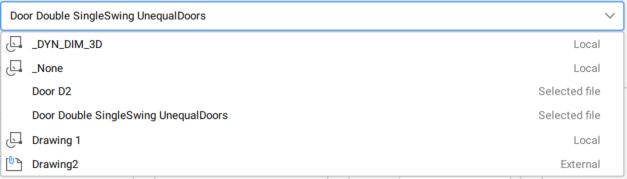
Name
Specifies the name of the block to insert, whose definition exists in the drawing, or the name of the file to insert as a block.
Browse
Opens the Select Drawing File dialog box that allows you to select a DWG, DXF, or RFA file from your computer or network.
Path
Displays the path to the file to insert as a block.
Insert external reference
Determines whether the block is inserted as a local or external reference.
Insertion Point
Specifies the insertion point of the block in the drawing.
- Specify On-screen
- Allows you to dynamically select the insertion point of the block in the current drawing.Note: Dynamic dimensions are displayed if Dynamic Input (DYN) is set to On (see the Dynamic dimensions article).
With DUCS set to On, use the Hotkey Assistant widget to change the number of dynamic dimensions displayed when placing the block. Press the Ctrl key to switch between the options Always show 2 dynamic dimensions and Show 4 dynamic dimensions when applicable.
 Note: The Hotkey Assistant widget is displayed if the HOTKEYASSISTANT system variable is set to 1 and the Display Hotkey Hints for INSERT options checkbox is ticked in the Hotkey Assistant Configuration dialog box (see the Hotkey Assistant widget article).
Scale
Scales the block.
- Specify On-screen
- Allows you to dynamically scale the block in the current drawing.
- Input coordinates
- Defines the scaling of the block.
- X
- Allows you to specify the scale factor along the X axis. Enter a negative value to mirror the block about the Y axis.
- Y
- Allows you to specify the scale factor along the Y axis. Enter a negative value to mirror the block about the X axis.
- Z
- Allows you to specify the scale factor along the Z axis.
Note:- Values larger than 1 make the block larger.
- 1 inserts the block at actual size.
- Values smaller than 1 make the block smaller.
- Values less than zero flip the block, like mirroring it.
- Uniform scale
- Determines whether the same scale factor is used for all axes.Note: This option is activated by default when inserting blocks created with the Scale uniformity option activated (see the BLOCK command article).
Rotation
Specifies the rotation angle of the block about its insertion point, starting with the X-axis as 0 degrees.
- Specify On-screen
- Allows you to dynamically rotate the block in the current drawing.
Block preview
Displays a preview of the block.
Block unit
Performs the automatic scaling of the block with respect to the INSUNITS and INSUNITSSCALING system variables of the current drawing.
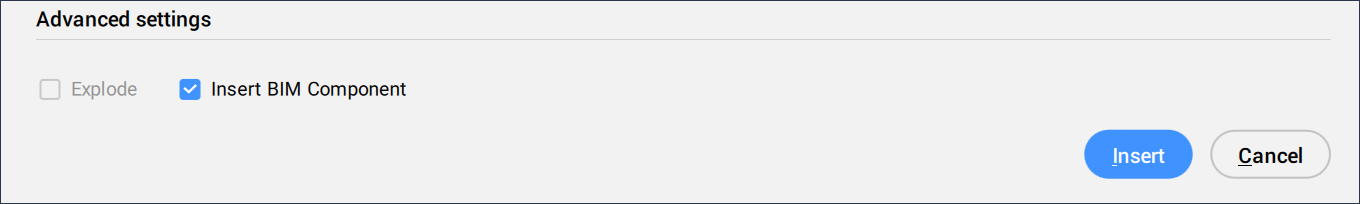
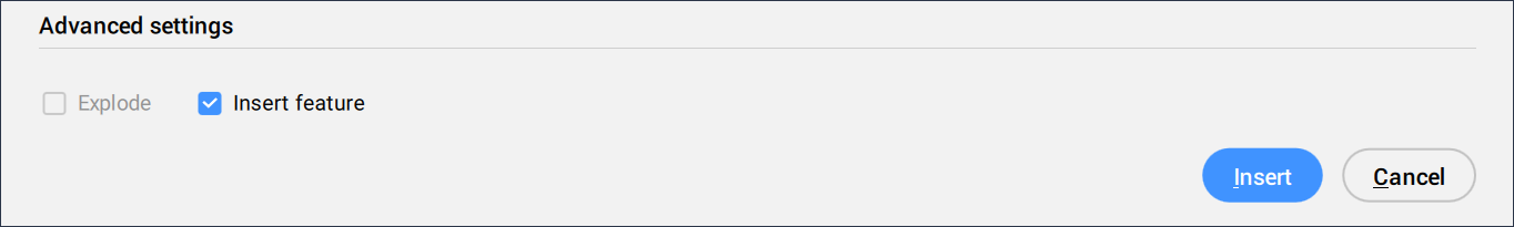
Advanced settings
Displays the available advanced settings, depending on the type of insert.
- Explode
- Determines whether to explode the inserted block.
- Insert BIM Component
- Determines whether to insert the block as a BIM Component.
 Note:
Note:- The Insert BIM Component option is available only if an external BIM Block is selected for insertion.
- This option is available for a BricsCAD BIM license. If you are using a BricsCAD Pro or a BricsCAD Mechanical license, the option becomes Insert feature.
- Insert feature
- Determines whether to insert the block as feature.
 Note:
Note:- The Insert feature option is available if an external mechanical block is selected for insertion.
- BricsCAD Pro or higher is required for this option.
- Insert Sheet Metal Form Feature
- Determines whether to insert the block as a sheet metal form feature.
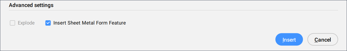 Note:
Note:- The Insert Sheet Metal Form Feature option is available only if a sheet metal form feature block is selected for insertion and the Model Space contains SM flanges.
- This option is available for a BricsCAD Pro license or higher.
- Use reference curves for insert
- Determines whether reference curves are used for insert.
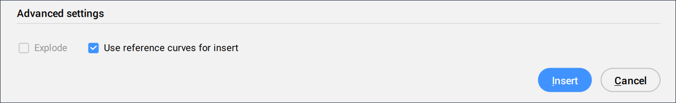 Note:
Note:- The Use reference curves for insert option is only available if the selected drawing contains reference curves. See also the Fuzzy insert guided workflow article.
- BricsCAD Pro or higher is required for this option.
- Use reference point for insert
- Determines whether a reference point is used for insert.
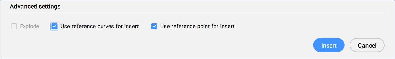 Note:
Note:- The Use reference point for insert option is only available if the selected DWG file contains a detail with guide curves. Details with guide curves can be created using the COPYGUIDED and MOVEGUIDED commands.
- It is available only when the Use reference curves for insert option is activated. Otherwise, the option becomes gray out.
- BricsCAD Pro or higher is required for this option.