Insert Block dialog box
The Insert Block dialog box allows you to insert parametric blocks into the current drawing. You can also insert entire DWG and DXF files as blocks into the drawing.
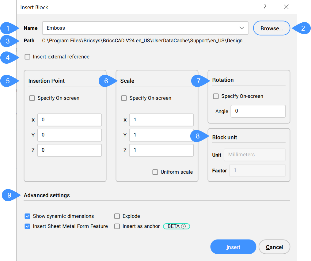
- Name
- Browse
- Path
- Insert external reference
- Insertion Point
- Scale
- Rotation
- Block unit
- Advanced settings
Name
Specifies the name of the block, whose definition exists in the drawing, or is a DWG or DXF file on the computer or network.
Browse
Selects a DWG or DXF file from your computer or network. Opens the Select Drawing File dialog box.
Path
Displays the path to the block, if the block was opened from a DWG or DXF file.
Insert external reference
Toggles whether the block is inserted as a local or external reference.
Insertion Point
Specifies the insertion point of the block in the drawing.
Scale
Scales the block:
- X, Y, Z: Defines the scaling of the block:
- X specifies the scale factor along the x axis. Enter a negative value to mirror the block about the y axis.
- Y specifies the scale factor along the y axis. Enter a negative value to mirror the block about the x axis.
- Z specifies the scale factor along the z axis.
- Uniform Scale: Toggles whether the same scale factor is used for all axes.
- Values larger than 1 make the block larger.
- 1 inserts the block at actual size.
- Values smaller than 1 make the block smaller.
- Values less than zero flip the block, like mirroring it.
Rotation
Specifies the rotation angle of the block about its insertion point, starting with the x-axis as 0 degrees.
Block unit
Controls the automatic scaling of the block with respect to the INSUNITS system variable of the current drawing.
Advanced settings
Displays the available advanced settings.
- Show dynamic dimensions
- Toggles whether to show in the drawing dynamic dimensions.
- Insert Sheet Metal Form Feature
- Toggles whether to insert sheet metal form feature. The Insert Sheet Metal Form Feature option is available only if the Model Space contains SM flanges.
- Insert BIM Component
- Toggles whether to insert BIM Components.Note: The Insert BIM Component option is available only if the Model Space contains BIM entities.
- Use reference curves for insert
- Toggles whether a reference curve is used for insert.
- Explode
- Toggles whether to insert the exploded block.
- Insert as anchor
- Anchors a block to a face of a solid. This anchor links the block to the face. The block will stay on the face when the host solid is moved or edited.