Passa attraverso una serie di sezioni trasversali per creare solidi o superfici 3D.
Icona:
Metodo
Selezionare sezioni trasversali in ordine di loft La forma del solido o della superficie 3D risultante è definita dalle sezioni trasversali.
Nota: È necessario specificare almeno due sezioni trasversali
Opzioni all'interno del comando
Modalità
Determina se l'inviluppo risultante è un solido o una superficie.
SOlido
Crea loft come solidi.
Nota: Solo per la modalità Solido, quando la variabile di sistema CREATESKETCHFEATURE è impostata su ON, le funzioni sketch per loft vengono create in un layer BC_SKETCHES dedicato, che non è visibile per default. Le funzioni schizzi per loft (schizzi, curve guida e percorsi) sono visibili e modificabili come riferimenti di blocco nel pannello Navigatore Meccanico. Inoltre, le proprietà delle funzioni di inviluppo sono presenti nel pannello Navigatore Meccanico.
Nota: La variabile di sistema CREATESKETCHFEATURE può essere controllata anche premendo il pulsante interruttore CreateSketchFeature nella barra multifunzione.
Superficie
Crea loft come superfici.
Crea
Crea un'entità loft. Opzione predefinita.
Sottrai
Sottrae l'entità di loft dai solidi o dalle superfici che si intersecano con essa.
Unisci
Unisce l'entità di loft con i solidi o le superfici che la intersecano.
Nota: Le opzioni Sottrai e Unisci sono disponibili solo per le entità di loft solide create quando la variabile di sistema CREATESKETCHFEATURE è impostata su ON.
Nota: Se l'Assistente Tasti di scelta rapida (HKA) è attivato, viene visualizzato il widget Assistente Tasti di scelta rapida, che indica se il comando è in modalità Crea, Sottrai o Unisci. Premere ripetutamente il tasto Ctrl durante la visualizzazione dinamica dell'estrusione per scorrere le varie opzioni.
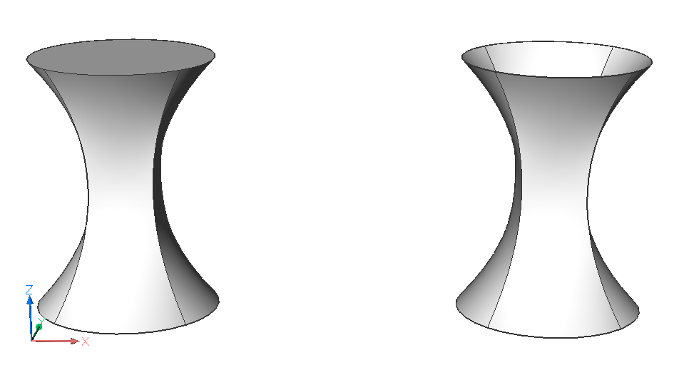
Guide
Utilizza sia le sezioni trasversali che le curve guida tra le sezioni trasversali selezionate per creare il loft.
Nota:
Quando la variabile di sistema DELOBJ è impostata su 2, le entità guida selezionate vengono eliminate.
Le curve guida non valide vengono ignorate. Se le curve guida non sono più valide dopo la modifica, la geometria viene ripristinata allo stato originale.
Traiettoria
Specifica la curva del percorso.
solo sezioni trasVersali
Utilizza solo entità di sezione trasversale per creare il loft e nessuna guida.
impostaZioni
Imposta le variabili che influiscono sul modo in cui viene costruito il loft.
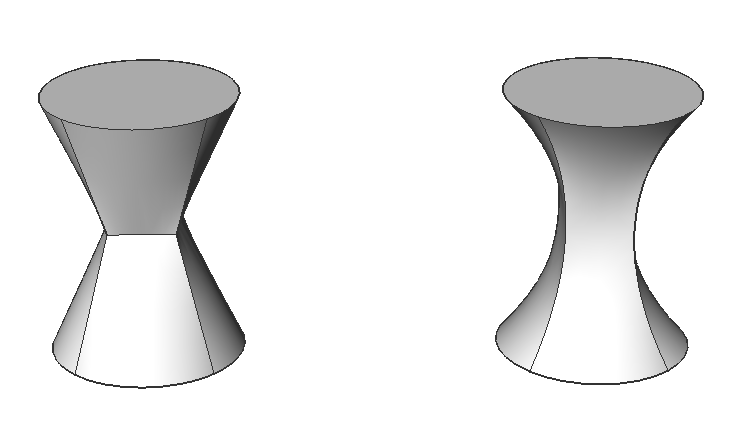
Rigata
Disegna superfici diritte tra le sezioni trasversali, presenta spigoli vivi in corrispondenza di ciascuna sezione trasversale.
Nota: Quando la proprietà Rigata è impostata su On, la proprietà Tipo normale diventa di sola lettura.
Levigata adattata
Disegna superfici lisce tra le sezioni trasversali.
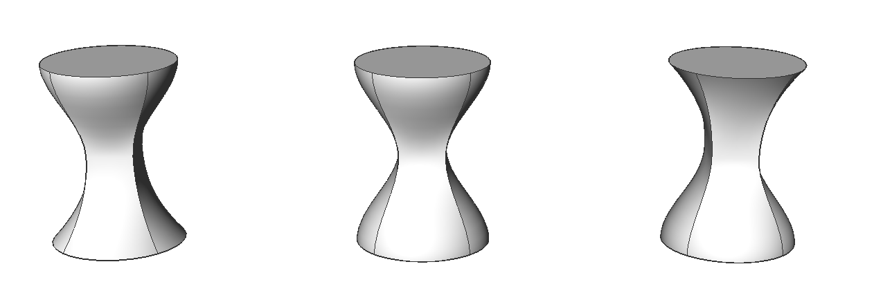
Normale a
Disegna le superfici normali alle sezioni trasversali scelte. Selezionare una delle opzioni per ottenere uno dei seguenti risultati:
Inizio
Entrambi
Fine
Tutto
Nota: Le entità LOFT create lungo una guida o un percorso mentre la variabile di sistema CREATESKETCHFEATURE è impostata su ON hanno la proprietà Tipo normale del pannello Navigatore Meccanico in sola lettura.
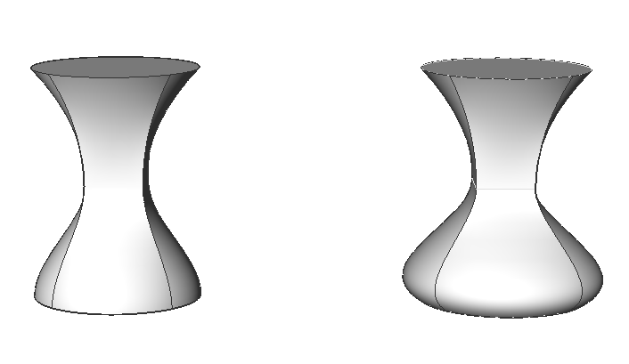
angoli di Sformo
Specifica gli angoli in corrispondenza delle sezioni trasversali iniziale e finale per modificare la forma del loft.
Nota: L'opzione angolo consente di specificare l'angolo di partenza dell loft da una sezione trasversale. L'opzione ampiezza imposta la distanza relativa della superficie dalla sezione trasversale nella direzione dell'angolo di sformo prima che la superficie inizi a piegarsi verso la sezione successiva.


 nella barra multifunzione.