TINEDITA
Edita una superficie TIN

Icone: 


Descrizione
Consente di modificare le Superfici TIN esistenti. Le opzioni di modifica influiscono sul modo in cui gli spigoli TIN collegano i punti TIN per formare triangoli. È inoltre possibile eliminare i punti TIN e gli spigoli esistenti o aggiungerne di nuovi o modificare la posizione e la quota altimetrica dei punti TIN esistenti.
Qualsiasi operazione di modifica della Superficie TIN può essere editata nel pannello Esplora Civile dopo l'esecuzione. È inoltre possibile modificare l'ordine cronologico delle operazioni di modifica.
Opzioni all'interno del comando
- AGgiungi Punti
- Aggiunge nuovi punti alla Superficie TIN esistente.Nota: Queste entità vengono aggiunte alla Superficie TIN come definizioni oggetti di disegno.
- aggiungi GRuppi di punti
- Aggiunge punti civili da un gruppo di punti specificato alla Superficie TIN esistente.Nota: Per impostazione predefinita, i punti Civili vengono posizionati nel gruppo di punti "_All points". Utilizzare il comando GRUPPOPUNTICIVILI per creare un nuovo gruppo di punti.
Viene visualizzata una finestra di dialogo:
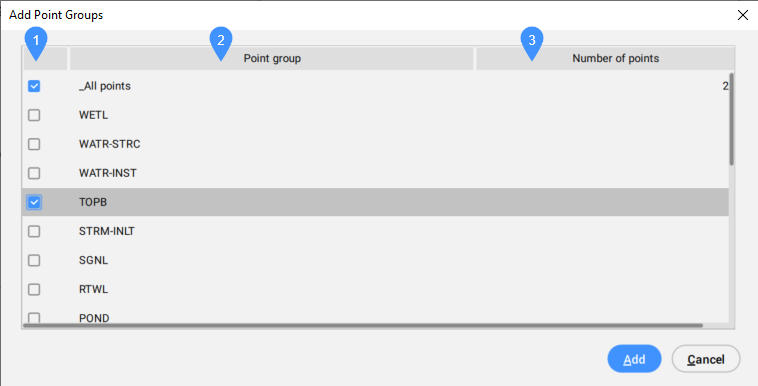
- Caselle di selezione
- Gruppi di punti
- Numero di punti
- Caselle di selezione
- Consente di selezionare o deselezionare un gruppo di punti da includere.
- Gruppi di punti
- Elenca tutti i gruppi di punti disponibili.
- Numero di punti
- Visualizza il numero di punti nel gruppo di punti.
- aggiungi LInee di discontinuità
- Aggiunge gli oggetti CAD lineari selezionati alla Superficie TIN come linee di discontinuità.
- Viene visualizzata una finestra di dialogo:
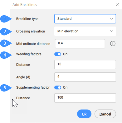
- Tipo linea di discontinuità
- Elevazione intersezioni
- Distanza media delle ordinate
- Fattori di sfoltimento
- Fattore di integrazione
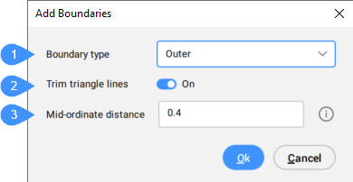
- Aggiungi COntorni
- Aggiunge gli oggetti CAD lineari selezionati alla Superficie TIN come contorni.
- Viene visualizzata una finestra di dialogo:
- RImuovi punti
- Rimuove punti/vertici di triangoli dalla Superficie TIN.
- INverti spigolo
- Scambia gli spigoli TIN selezionati.Nota: Gli spigoli non possono essere scambiati nei seguenti casi:
- quando gli spigoli TIN giacciono sulle linee di discontinuità.
- quando gli spigoli TIN vengono creati con la definizione Aggiungi linea.
- quando lo spigolo TIN appartiene a due triangoli adiacenti che formano un inviluppo concavo.
- POsizione del punto
- Modifica la posizione di uno o più punti TIN in un unico passaggio.
- ELevazione punto
- Modifica la quota altimetrica di uno o più punti TIN in un unico passaggio.
- aggiuNgi nuova linea
- Aggiunge un nuovo spigolo TIN tra i punti TIN esistenti.
- Elimina linea
- Elimina gli spigoli TIN all'interno dell'area di selezione specificata.Nota: I bordi all'interno dell'area selezionata sono colorati in rosso.
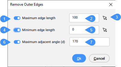
- rimuovi spigoli ESterni
- Rimuove i triangoli sul contorno esterno della superficie TIN che hanno:
- lunghezza massima spigolo.
- lunghezza minima spigolo.
- angolo massimo adiacente.
È possibile specificare quale di questi criteri viene preso in considerazione durante la rimozione degli spigoli esterni.
Questo metodo inizia a rimuovere i triangoli dal contorno esterno verso la parte interna della superficie TIN. Interrompe la rimozione dei triangoli, quando l'ultimo triangolo esterno soddisfa i criteri specificati. Ciò significa che questo metodo non rimuove i triangoli interni.
Viene visualizzata una finestra di dialogo:
- Minimizza aree piatte
- Trova i triangoli piatti e quindi scambia gli spigoli TIN adiacenti di tali triangoli in modo che la loro pendenza sia diversa da zero.
Questo metodo è particolarmente utile quando la superficie TIN viene creata da Curve di livello. Inizia dal lato concavo delle curve di livello e scambia lo spigolo del primo triangolo in modo che la sua pendenza diventi diversa da zero. Il processo continua fino a quando il metodo non garantisce ancora che non ci siano triangoli piatti scambiando i loro bordi.
Nota: Il metodo Minimizza aree piatte consente di scorrere solo gli spigoli TIN che non si trovano sulle linee di discontinuità.
- Rimuovi elevazioni
- Rimuove i punti TIN al di sotto/al di sopra della quota altimetrica specificata e visualizza il numero di punti rimossi.
Viene visualizzata una finestra di dialogo:
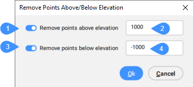
- Rimuovere punti sopra elevazione
- Elevazione superiore a
- Rimuovere i punti sotto l'elevazione
- Elevazione inferiore a
- Rimuovi punti sopra elevazione
- Commuta l'opzione per rimuovere i punti TIN al di sopra di una quota altimetrica specificata.
- Elevazione maggiore di (2)
- Imposta la quota altimetrica al di sopra della quale i punti TIN vengono rimossi.
- Rimuovi i punti sotto l'elevazione
- Commuta l'opzione per rimuovere i punti TIN al di sotto di una quota altimetrica specificata.
- Elevazione minore di (4)
- Imposta la quota altimetrica al di sotto della quale vengono rimossi i punti.
- Alza o Abbassa
- Regola le elevazioni di una superficie TIN aggiungendo o sottraendo una quantità specificata da tutti i punti.
- Levigatura
- Apre la finestra di dialogo Leviga Superficie consente di levigare una superficie TIN aggiungendo altri punti.