スケッチベースフィーチャー
スケッチベースフィーチャーは、3Dソリッドの作成に使用した 2D図形を編集し、3Dソリッドを自動的に更新できるBricsCADフィーチャーです。
押し出し、ロフト、スイープ、回転コマンドとその子フィーチャーのSUBTRACT、およびUNITEコマンドは、CREATESKETCHFEATUREシステム変数がオンの場合にスケッチフィーチャーを作成します。これらは、メカニカルブラウザパネルで使用できます。
3Dソリッドを作成
- CREATESKETCHFEATUREシステム変数をオンにします。
- 閉じたポリラインなどの2D図形を作図します。
- (オプション)パラメトリックをスケッチ図形に追加します。
- EXTRUDE、LOFT、SWEEP、またはREVOLVEコマンドを起動して、3Dソリッドを作成します。
対応するスケッチ図形を編集して3Dソリッドを編集
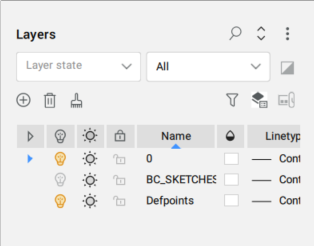
スケッチ図形は、2D図形からブロックとして作成され、新しい画層BC_SKETCHESに移動されます。この画層はデフォルトでオフになっています。
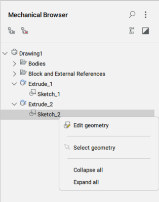
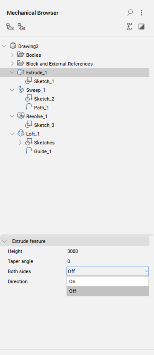
すべてのスケッチベースフィーチャは、メカニカルブラウザパネルに表示されます。
- 方法1
-
スケッチ図形を編集するには、メカニカルブラウザパネルで図形を右クリックし、ジオメトリを編集を選択します。
スケッチフィーチャの変更を保存すると(BCLOSEコマンド)、3Dソリッドが自動的に更新されます。
- 方法2
-
スケッチフィーチャを編集するには、BEDITコマンドを使用してブロック定義の作成または編集ダイアログボックスを開き、そこからスケッチフィーチャを選択してブロック編集で開くこともできます。
スケッチベースフィーチャーソリッドを修正するには、次の2つの方法があります。
- 方法1
-
メカニカルブラウザでソリッドをクリックし、メカニカルブラウザパネルの下部でプロパティを調整します。
- 方法2
- UPDATESKETCHコマンドを起動し、コマンドラインでフィーチャの名前、パラメータの名前、および新しい値を指定します。