TIN [TINサーフェス]
選択したソースデータから新しいTINサーフェスを作成します。

アイコン:
説明
TINサーフェスは、地形または土木フィーチャーの3次元幾何学的表現であり、三角形、等高線、傾斜、高さ範囲による表現も含んでいます。
このアルゴリズムは、ドロネー三角分割法を使用して不規則三角形網(TIN)を形成する三角形に、最も近い点を接続します。
TINサーフェスに境界と破断線を追加することで、点の接続方法に影響を与えることができます。三角形は常に指定された境界と破断線に従い、交差することはありません。TINサーフェスは、TINEDITコマンドで使用可能な他のオプションを使って編集することもできます。
TINサーフェスは、ポイントファイル、ポイントグループ、ポイントクラウド、Civilポイント、等高線など、ほとんどの入力データに動的にリンクされます。ポイントファイルと点群は、通常、それらからTINサーフェスが作成された後、ユーザーによって変更されなくなりました。したがって、TINサーフェスの作成後の次の手順では、TINサーフェスのスナップショットが自動的に作成されます。これにより、入力データへのリンクが解除されます。土木エクスプローラでスナップショットを作成定義を削除して、ダイナミックリンクを再確立できます。
ダイナミック リンクは、CAD要素と3D面ではサポートされていません。これらのタイプの入力データを変更しても、TINサーフェスの三角形分割には影響しません。
使用方法
次のタイプのソース データを使用して、TINコマンドでTINサーフェスを作成できます。
- CAD要素(ポイントおよび線形図形)およびシビルポイント
- ポイントファイル
- 図面で指定された市民ポイント
- 3D面要素から。
- 点群
- ポイント グループ
- 輪郭
TINコマンドは、リボン、土木ツールバー、コマンドライン、または土木エクスプローラパネルから起動します。ソースデータ型を選択し、入力要素を指定します。新しいデータが新しい定義としてTINサーフェスに追加されます。
コマンドオプション
- TINサーフェスを作成する図形を選択、または
- 選択した図面図形/オブジェクトからTINサーフェスを作成します。
線形オブジェクトから TIN サーフェスを作成する場合、コマンドラインで、線形図形の適用方法をポイント、エッジ、破断線から選択するよう求められます。
直線図形を破断線として適用することを選択した場合、新しい 破断線を追加がTINサーフェスに追加されます。この場合、コマンドラインは、除草と補足のパラメーターを指定するように求めます。破断線タイプ、交差標高、中間座標距離など、その他の一部のパラメーターは事前に定義されています。これらは、破断線を追加ダイアログボックスの土木エクスプローラパネルで簡単に変更できます。
それ以外の場合、選択した線形オブジェクトは、TINサーフェス ポイントまたはエッジとして図面オブジェクトを追加定義に追加されます。
- ファイルから読み込み
- 選択したポイントファイルからTINサーフェスを作成します。コマンドラインでこのオプションを選択すると、ポイントファイルからTINサーフェスを作成ダイアログボックスが開き、ポイントファイルと適切なポイントファイル形式を選択できます。定義済みのポイントファイル形式が適切でない場合は、カスタムファイル拡張子、区切り文字、コメントタグ、および列を使用して独自の形式を定義できます。ファイルを選択すると、TINサーフェスの作成に使用するポイントを単純化および高密度化するオプションが表示されます。
- ポイントを配置
- TINポイントの指定した位置と標高からTINサーフェスを作成します。
- 基点を選択
- TINポイントの位置を指示します。
- 高さを入力
- TINポイントの標高を入力します。
- 面から作成
- 選択した3D面要素からTINサーフェスを作成します。
3D面をエッジおよび表示として適用オプションを選択すると、3D面要素の頂点とエッジが三角形分割に使用されます。したがって、TINサーフェスの三角形は3D面と重なります。3D面要素の外側のエンベロープの形状も保持されます。それ以外の場合は、3D面要素の頂点のみが三角測量に使用されます。これは、TINサーフェスが常に3D面要素と重なるとは限らないことを意味します。また、TINサーフェスの外側の境界が凸形状になるように、3D面要素の外側のエンベロープに追加の三角形が作成されます。
- 点群から作成
- 選択した点群からTINサーフェスを作成します。
- TINサーフェスを単純化しますか?
- はい:以下で説明する、指定された簡略化パラメータに基づいてTINサーフェスの作成に使用されるソースポイントを簡略化します。
- 簡略化のための半径ステップ:ソースポイントのセット全体に広がる仮想グリッドを形成するセルサイズ。各セル内で、標高差が指定された最大値より大きいすべてのポイントが削除/簡略化されます。
- 標高差:TINサーフェス上の隣接ポイント間の最大標高差。標高差が大きいすべてのポイントは、TINサーフェスから除外されます。
- TINサーフェスを作成
- TINサーフェスを作成します。
- 再び簡素化
- 新しく提案された単純化パラメータを使用してTINサーフェスを単純化し、最初の反復よりも多くのポイントが削除されるようにします。
- TINサーフェスを高密度化
- はい:TINサーフェスを単純化した後、TINサーフェス内の指定したエリアで、単純化されたTINサーフェスと除外された入力ポイントとの間の最大許容 標高差 が指定されます。指定した値よりも高さの差が大きいすべての入力ポイントは、簡略化されたTINサーフェスに戻して追加されます。
なし:TINサーフェスは、単純化パラメータに指定されたパラメータに従って作成されます。
- ポリゴンの選択
- 選択したポリゴン内のTINサーフェスを高密度化します。
- ポリゴンを作図
- 描画されたポリゴン内のTINサーフェスを高密度化します。
- TINサーフェス全体に対して入力
- TINサーフェス全体を高密度化します。
注: 簡略化および高密度化プロセスの詳細については、「TIN 簡略化」および「TIN 高密度化」を参照してください。
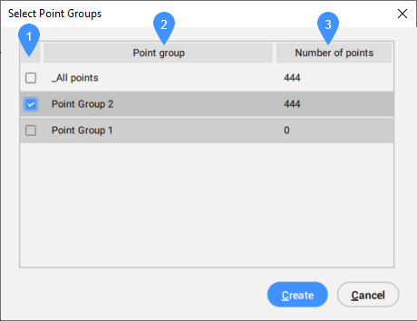
- ポイントグループから作成
- 選択したポイント グループからTINサーフェスを作成します。
- 等高線から作成
- 選択したライン線要素からTINサーフェスを作成します。
- 間引き係数を使用しますか?
-
はい: 既存の等高線頂点間の距離と角度が、指定した除草パラメータよりも小さい場合、既存の等高線頂点はTINサーフェスの作成に使用されません。
なし:ソースライン要素のすべての頂点を使用して、コンターからTINサーフェスを作成します。
- 補足係数を使用する
-
Yes: コンター上の頂点間の距離が指定された補足距離よりも大きい場合、追加の頂点がコンターに追加されます。
なし:ソースライン要素のすべての頂点を使用して、コンターからTINサーフェスを作成します。
- メッシュから作成
- メッシュまたはポリフェースメッシュ図形からTINサーフェスを作成します。
- ポリゴンをクリップ
- TINサーフェスにクリップ境界を追加します。
- ポイントグループから作成
- 選択したポイント グループからTINサーフェスを作成します。
- 等高線から作成
- 選択したライン線要素からTINサーフェスを作成します。
- 間引き係数を使用しますか?
-
はい: 既存の等高線頂点間の距離と角度が、指定した除草パラメータよりも小さい場合、既存の等高線頂点はTINサーフェスの作成に使用されません。
なし:ソースライン要素のすべての頂点を使用して、コンターからTINサーフェスを作成します。
- 補足係数を使用する
-
Yes: コンター上の頂点間の距離が指定された補足距離よりも大きい場合、追加の頂点がコンターに追加されます。
なし:ソースライン要素のすべての頂点を使用して、コンターからTINサーフェスを作成します。
- ポリゴンをクリップ
- TINサーフェスにクリップ境界を追加します。注: クリップポリゴンの詳細については、「TINEDIT コマンドでの TIN 定義」を参照してください。


