Fizyczne Materiały
Otwieranie okna dialogowego Materiały fizyczne
- Uruchom polecenie BLMATERIAŁY.
- Użyj menu podręcznego w panelu Kompozycje BIM i wybierz opcję Otwórz okno dialogowe materiału.
- Kliknij przycisk Przeglądaj (
 ) właściwości Materiału w Przeglądarce Mechanicznej dla wybranego komponentu.
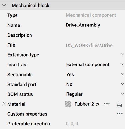
Tworzenie materiałów fizycznych
Materiały fizyczne można tworzyć w bazie danych projektu lub centralnej bazie danych. Możesz tworzyć nowe materiały od podstaw lub kopiować je z już istniejących.
Tworzenie fizycznego materiału od podstaw
Po otwarciu okna dialogowego Materiały fizyczne wybierz materiał z listy materiałów w projekcie lub w centralnej bazie danych.
- Kliknij przycisk Nowy materiał (
 ) w oknie dialogowym Materiały fizyczne.
 - Kliknij prawym przyciskiem myszy i wybierz Nowy materiał z menu kontekstowego.
Do wybranej bazy danych zostanie dodany materiał o nazwie Nowy. Teraz możesz edytować nowy materiał.
Dodawanie materiału fizycznego jako kopii istniejącego materiału
- Kliknij prawym przyciskiem myszy materiał, który chcesz skopiować i wybierz Duplikuj z menu kontekstowego.
- Materiał o nazwie <existing_material>-2 zostanie dodany do wybranej bazy danych.
- Edytuj kopię materiału.
Edycja materiału fizycznego
- Identyfikator: można edytować nazwę, klasę i opis materiału.
- Wygląd: można edytować sposób renderowania materiału w widokach Przekrój, Elewacja i 3D.
- Właściwości: możesz edytować właściwości materiału w kategoriach Informacje, Fizyczne i BIM.
Wybierz materiał, który chcesz edytować z listy W projekcie lub W centralnej bazie danych w oknie dialogowym Materiały fizyczne.
Strona zakładki Identyfikator
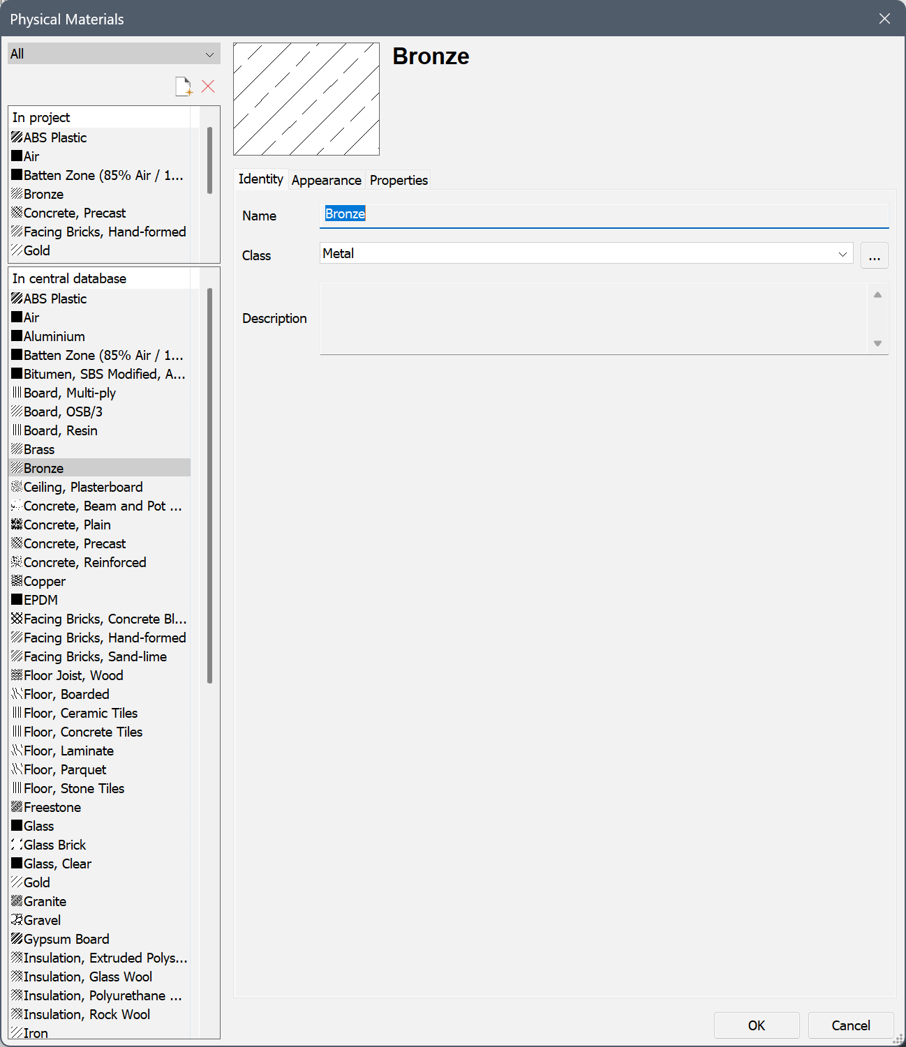
- Wpisz Nazwę materiału.
- Wybierz Klasę z listy rozwijanej *.
- (Opcjonalnie) Wpisz Opis.
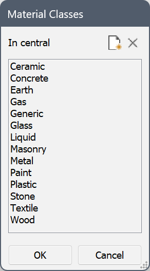
* Kliknij przycisk Przeglądaj ( ) w pobliżu menu rozwijanego Klasa, aby otworzyć okno dialogowe Klasy materiałów, w którym można utworzyć nowe klasy materiałów.
Strona karty Wygląd
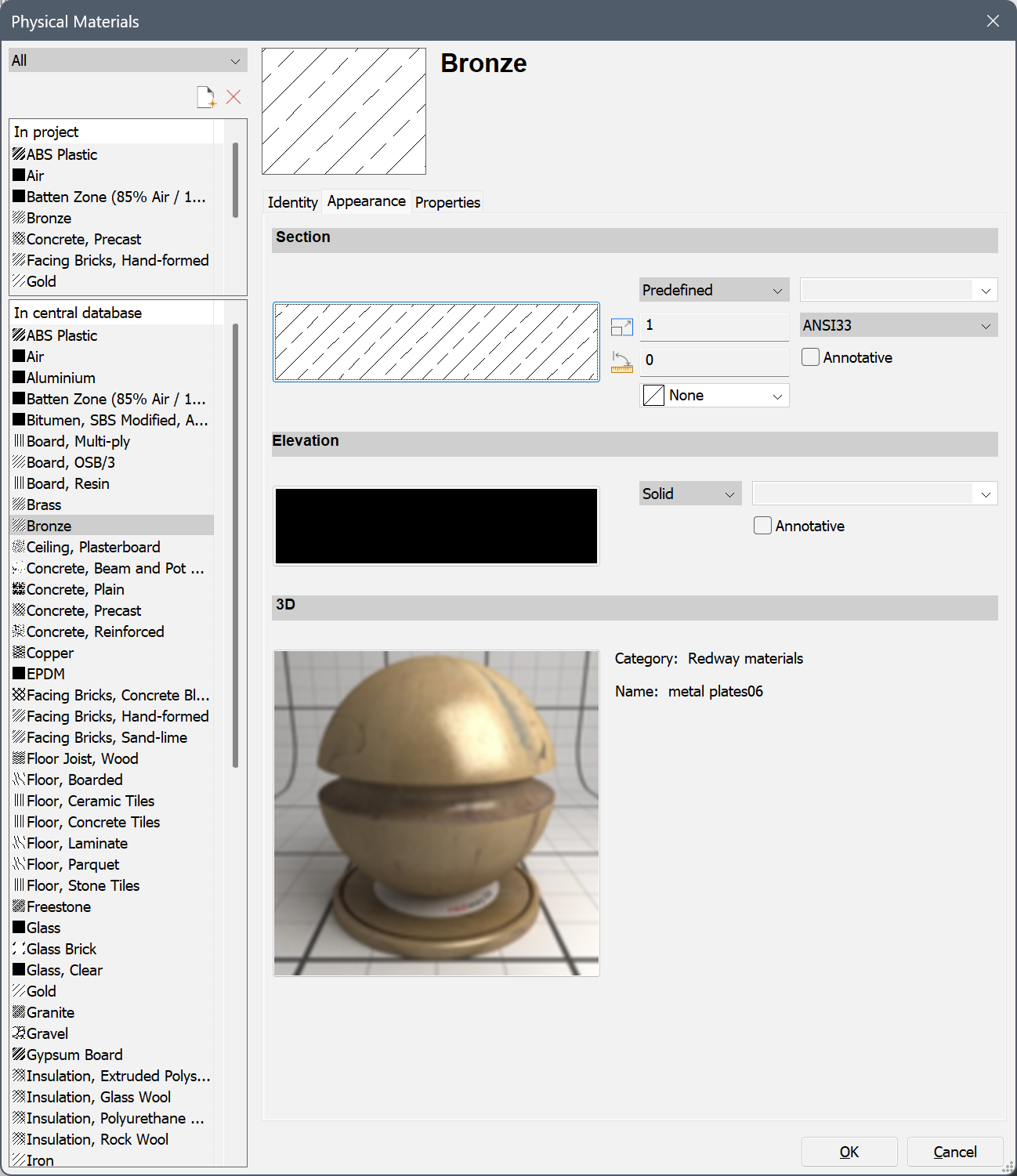
- Ustawienia Sekcji
Ustawienia Przekroju definiują wypełnienie linii granicznych przekroju w wygenerowanych przekrojach 2D.
- Kliknij menu rozwijane Typ Wzoru Kreskowania i wybierz typ kreskowania: Brak, Bryła, Liniowy, Predefiniowany lub Niestandardowy.
- Wykonaj jedną z poniższych czynności, aby wybrać predefiniowany lub niestandardowy wzór kreskowania:
- Kliknij podgląd kreskowania i wybierz wzór w oknie dialogowym Wzór kreskowania przekroju.
- Kliknij menu rozwijane Nazwa Wzoru Kreskowania i wybierz wzorzec z listy.
- Zdefiniuj odstęp między wierszami za pomocą opcji Odstęp wzoru kreskowania (tylko dla czcionki liniowej ).
- Zdefiniuj Skala Wzoru Kreskowania.
Ostateczna skala wzoru w przekroju jest iloczynem ustawienia Skala materiału fizycznego i wartości właściwości Skala sekcji BIM. W rezultacie wydrukowana skala wzoru kreskowania jest niezależna od skali płaszczyzny przekroju.
- Ustaw Kąt Wzoru Kreskowania.
- W polu Warstwa wpisz nazwę lub kliknij przycisk strzałki i wybierz warstwę z listy.
- Opcjonalnie zaznacz opcję Krzyż (tylko dla typu Liniowego ).
- Opcjonalnie zaznacz opcję Opisowy.
- Opcjonalnie wybierz Kolor tła kreskowania dla wybranego wzoru kreskowania.
- Ustawienia Wysokości
Ustawienia Wysokość definiują wypełnienie wysokości linii tła przekroju w wygenerowanych przekrojach 2D. Ustawienie Generuj wypełnienie elewacji musi być aktywne na rzutni przekroju 2D, aby można było używać wypełnień elewacji.
Patrz ustawienia Sekcji powyżej, z wyjątkiem ustawienia Skala. Kreskowanie elewacji jest niezależne od właściwości Skala sekcji BIM.
- Ustawienia 3D
Ustawienia 3D definiują materiał renderowania, który zostanie użyty w modelu 3D.
Kliknij dwukrotnie obraz podglądu i wybierz materiał w oknie dialogowym Wybierz materiał do renderowania.
Strona karty Właściwości
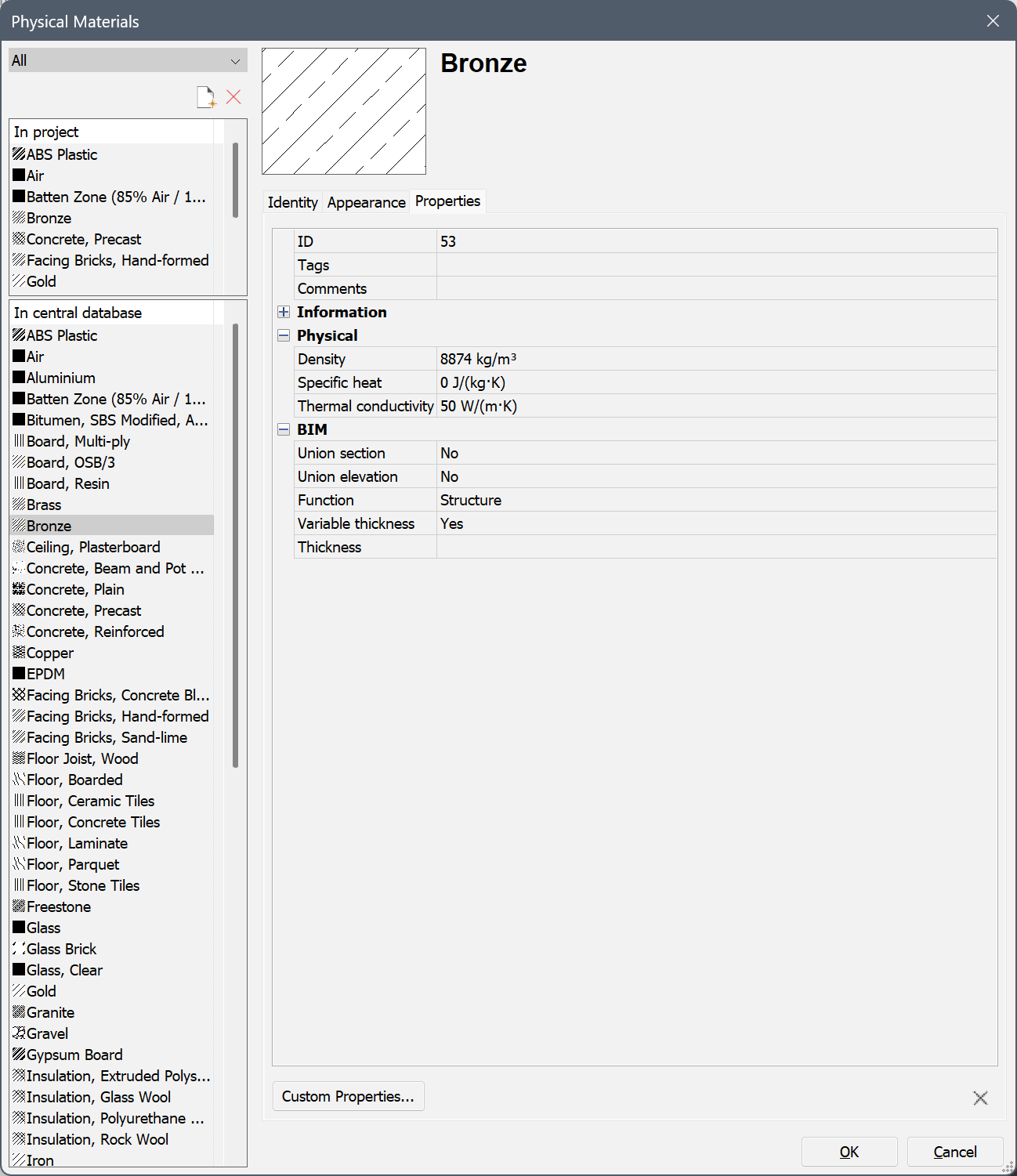
- Edytuj pole Tagi: tagi są oddzielone przecinkami.
W tagach rozróżniana jest wielkość liter.
Kliknij przycisk Przeglądaj (
 ), aby otworzyć okno dialogowe Tagi.
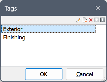
- Kliknij przycisk Nowa pozycja (
 ), aby dodać nowy tag na dole listy.
 - Wybierz tag z listy i kliknij przycisk narzędzia:
 : Edycja wybranego tagu.
 : Usuń tag.
 : Przesunięcie znacznika w górę.
 : Przesunięcie znacznika w dół.
- (Opcjonalnie) Rozwiń właściwości Informacje i wypełnij wymagane pola.
- (Opcjonalnie) Rozwiń Właściwości fizyczne i określ właściwości fizyczne materiału.
- Rozwiń właściwości BIM.
- Sekcja łącząca: Wybierz Tak, aby usunąć linie połączeń w sekcjach między różnymi bryłami tego materiału. Wybierz opcję Nie, aby zachować linie połączeń.
- Jednakowa wysokość: Wybierz Tak, aby usunąć linie połączeń w elewacjach między różnymi bryłami tego materiału. Wybierz opcję Nie, aby zachować linie połączeń.
- Wybierz Funkcję z listy rozwijanej.
- Zmienna grubość:
Wybierz Tak, aby zezwolić na zmienną grubość. Podczas nakładania kompozycji zawierającej materiał o zmiennej grubości na bryłę, grubość warstwy dostosuje się tak, aby całkowita grubość kompozycji odpowiadała grubości oryginalnej bryły.
Wybierz Nie, aby nie zezwalać na zmienną grubość. Podczas nakładania kompozycji, w której wszystkie warstwy mają stałą grubość na bryłę, grubość bryły zostanie dostosowana do grubości kompozycji.
- Wpisz domyślną grubość w polu Grubość.
- Kliknij przycisk OK.
Kopiowanie materiałów między projektem a centralnymi (bibliotecznymi) bazami danych
- Wybierz materiał(y) w źródłowej bazie danych.Naciśnij i przytrzymaj klawisz Ctrl, aby zaznaczyć wiele materiałów.

- Przeciągnij materiały do docelowej bazy danych.
Zestaw zaznaczeń zostanie skopiowany.
Jeśli jeden lub więcej materiałów istnieje już w docelowej bazie danych, wyświetlone zostanie okno alertu:
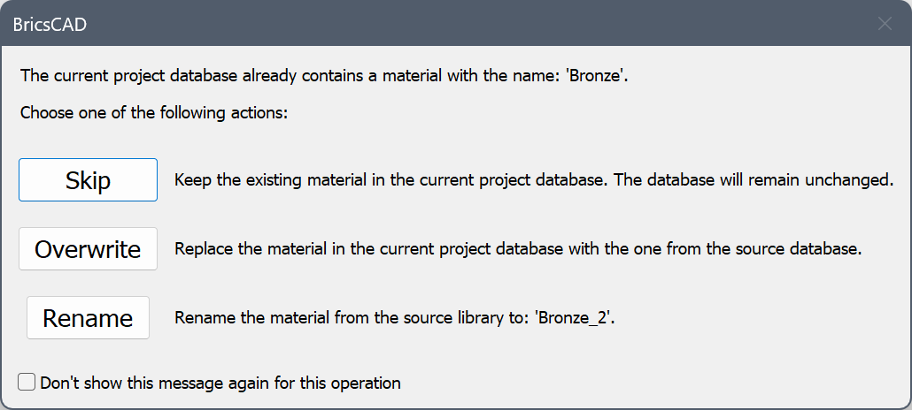
Kliknij odpowiedni przycisk, aby nadpisać, powielić lub pominąć istniejący materiał. Zduplikowane materiały mają numer indeksu dodany do ich nazwy.
Stosowanie materiałów fizycznych
- Dla brył i jednostek BIM
- Najpierw dodaj materiał fizyczny do kompozycji jako warstwę, a następnie zastosuj tę kompozycję do jednostki:
- Otwórz okno dialogowe Kompozycje (polecenie BLKOMPOZYCJE).
- Utwórz nową kompozycję BIM (przycisk Nowa kompozycja) lub wybierz kompozycję z listy, aby ją edytować.
- Kliknij przycisk Dodaj warstwę.
Zostanie otwarte okno dialogowe Materiały fizyczne.
- Wybierz materiał i kliknij OK.
- Kliknij przycisk OK, aby zamknąć okno dialogowe Kompozycje.
- Zastosuj kompozycję:
- Użyj polecenia BIMWSTAWKOMPOZYCJĘ.
- Przeciągnij i upuść kompozycję z panelu Kompozycje BIM na jednostkę.
- Dla komponentów mechanicznych
- Zastosuj materiał fizyczny za pomocą panelu Przeglądarka Mechaniczna:
- Otwórz panel Przeglądarka Mechaniczna (polecenie OTWÓRZPRZEGMECHANICZNĄ).
- Wybiera komponent.
- Znajdź właściwość Materiał komponentu.
- Kliknij przycisk Wybierz materiał obok materiału.
Zostanie otwarte okno dialogowe Materiały fizyczne.
- Wybierz materiał fizyczny i kliknij OK.
Usuwanie materiałów fizycznych
- W oknie dialogowym Materiały fizyczne wybierz materiał (y) w bazie Danych Projektu lub Biblioteki.
- Kliknij Usuń.

