Panel Przeglądarki Mechanicznej
Aby otworzyć panel Przeglądarkę Mechaniczną, uruchom polecenie OTWÓRZPRZEGMECHANICZNĄ lub kliknij prawym przyciskiem myszy panel/pasek narzędzi wstążki i wybierz Przeglądarke Mechaniczną z listy Panele.
Panel Przeglądarka Mechaniczna oferuje centralną lokalizację do przeglądania i modyfikowania właściwości parametrycznych części mechanicznych i zespołów.

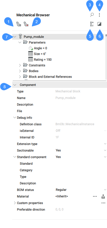
- Grupuj przez obiekty
- Grupuj przez typ
- Pokaż wyszukiwanie
- Ustawienia
- Sortuj alfabetycznie
- Pokaż wybrane
- Lista podmiotów mechanicznych
- Właściwości
Grupuj przez obiekty
Grupuje ograniczenia 3D według jednostek. Rozwiń podmiot, aby wyświetlić powiązane z nim ograniczenia.
Grupuj przez typ
Grupuje ograniczenia 3D według typu. Rozwiń ograniczenie, aby wyświetlić podmioty, których ono dotyczy.
Pokaż wyszukiwanie
Otwiera pole wyszukiwania i powiązane narzędzia.
- Pole wyszukiwania
- Przeszukuje drzewo przeglądarki mechanicznej w poszukiwaniu wprowadzonego ciągu znaków. Wyszukiwanie działa jak filtr, dzięki czemu przeglądarka pokazuje wszystkie komponenty, których nazwy lub nazwy komponentów (lub część nazw lub nazw komponentów) pasują do ciągu znaków. Naciśnij X po prawej stronie pola wyszukiwania, aby je zamknąć.
Ustawienia
- Wyrażenia wiązań
- Określa, czy wyświetlana jest wartość liczbowa, czy przypisana nazwa parametru.
- Parametry komponentów
- Kontroluje widoczność parametrów podkomponentów.
- Wyrażenia parametrów komponentów
- Kontroluje wizualną reprezentację parametrów podkomponentu: wartość liczbowa lub przypisana nazwa parametru.
- Podskładniki standardowych części
- Kontroluje widoczność podzespołów standardowych części, które są zespołami mechanicznymi.
- Szyki elementów
- Przełącza wyświetlanie węzłów Array w drzewie przeglądarki, w tym tablic Components.
- Bloki i Odnośniki Zewnętrzne
- Przełącza wyświetlanie węzłów Bloki i Odniesienia zewnętrzne w drzewie przeglądarki. Przełącza także tworzenie węzłów w folderze Bryły dla obiektów Bloków.
- Zawsze synchronizuj wybór
- Przełącza synchronizację węzłów wyboru w Przeglądarce Mechanicznej z wyborem odpowiednich obiektów w przestrzeni modelu. Gdy obiekt zostanie usunięty z zaznaczenia, zaznaczone pozostaną tylko węzły odpowiadające obiektom pozostałym w zaznaczeniu. Jeśli żaden obiekt nie jest zaznaczony, zaznaczony zostanie węzeł główny (podobnie jak w przypadku otwarcia dokumentu).
- Zachowaj kolejność listy wartości
- Przełącza sortowanie listy wartości dla parametrów wewnątrz listy rozwijanej.
- Wybór podświetlenia
- Przełącza podświetlenie wybranych elementów na rysunku.
- Asynchroniczne ładowanie właściwości
- Kontroluje, czy Przeglądarka Mechaniczna zbiera właściwości asynchronicznie, jeśli w drzewie Przeglądarki Mechanicznej zaznaczony jest więcej niż jeden węzeł.
- Uwidocznij wszystkie bryły
- Przełącza wyświetlanie brył dla bloków mechanicznych i brył niezwiązanych z ograniczeniami w folderze Bryły.
Sortuj alfabetycznie
Lista komponentów mechanicznych i ograniczeń 3D w porządku alfabetycznym. W przeciwnym razie są one wymienione w kolejności, w jakiej zostały dodane do zespołu.
Pokaż wybrane
Po włączeniu wyświetlane są tylko węzły odpowiadające wybranym obiektom lub ich rodzicom.
Po włączeniu tej opcji, gdy żaden obiekt nie jest zaznaczony lub zaznaczenie jest usunięte, w przeglądarce wyświetlany jest pełny model.
Stan trybu Pokaż wybrane jest zapamiętywany między sesjami i jest taki sam dla wszystkich otwartych dokumentów.
Lista podmiotów mechanicznych
Wyświetla hierarchiczną listę drzewiastą elementów mechanicznych, takich jak parametry użytkownika, ograniczenia, części, tablice i funkcje. Węzły najwyższego poziomu mogą mieć podwęzły. Na przykład węzeł ograniczenia ma podwęzły dla swoich argumentów. Węzeł tablicy ma podwęzły dla swoich argumentów itp.
Kliknij dwukrotnie węzeł, aby go rozwinąć lub zwinąć, kliknij dwukrotnie węzeł, aby edytować jego etykietę. Nie wszystkie nazwy węzłów mogą być edytowane.
Każdy węzeł na liście ma powiązane menu kontekstowe. Kliknij węzeł prawym przyciskiem myszy, aby wywołać menu. Zawartość menu może być różna dla każdego rodzaju węzła. Można także wybrać grupę węzłów i wywołać dla nich menu kontekstowe. Menu będzie zawierać tylko te elementy, które mają zastosowanie do każdego wybranego węzła.
Menu kontekstowe komponentu głównego zawiera następujące elementy:
- Aktualizuj
- Aktualizuje hierarchię komponentów mechanicznych dla bieżącego rysunku w przypadku, gdy odwołujące się pliki rysunków komponentów podrzędnych zostały zmodyfikowane.
- Styl wizualny > Wszystko według rzutni
- Stosuje bieżący styl wizualny do wszystkich komponentów w zespole.
- Przełącz wszystkie na lokalne
- Konwertuje wszystkie zewnętrzne komponenty w modelu na komponenty lokalne.
- Przełącz wszystkie na zewnętrzne
- Przełącza wszystkie wewnętrzne komponenty na komponenty zewnętrzne.
- Dodaj nowy parametr
- Tworzy nowy parametr w zespole.
- Właściwości użytkownika
- Otwiera okno dialogowe Właściwości mechaniczne w celu zdefiniowania niestandardowych właściwości rysunku.
- Zaznacz wszystko
- Wybiera wszystkie komponenty o tej samej definicji.
- Wybierz jednakowe
- Wybiera wszystkie komponenty o tej samej nazwie i tych samych wartościach parametrów.
- Podświetl wszystko
- Podświetla wszystkie komponenty o tej samej definicji.
- Podświetl jednakowe
- Podświetla wszystkie komponenty o tej samej nazwie i tych samych wartościach parametrów.
- Utwórz sekwencję
- Tworzy blok z reprezentacją bieżącego złożenia.
- Przelicz węzły podrzędne
- Ponownie wylicza wszystkie węzły podrzędne według ich typów.
- Wyliczanie węzłów podrzędnych w sposób ciągły
- Ponownie wylicza wszystkie węzły podrzędne z ciągłą numeracją, jeśli ma to zastosowanie.
- Zamknij wszystko
- Zwija główny komponent oraz wszystkie komponenty i podkomponenty.
- Rozwiń wszystko
- Rozwija główny komponent oraz wszystkie komponenty i podkomponenty.
Menu kontekstowe dla komponentów podrzędnych (innych niż root), wewnętrznych lub zewnętrznych, również oferuje:
- Otwórz
- Otwiera przywołany rysunek (patrz polecenie BMOTWÓRZ).
- Otwórz kopię
- Otwiera kopię wstawki komponentu jako nowy rysunek (patrz polecenie BMOTWÓRZKOPIĘ).
- Aktualizuj
- Przeładowuje wszystkie komponenty z plików zewnętrznych i aktualizuje tabele BOM (patrz polecenie BMAKTUALIZUJ).
- Zastąpić...
- Zastępuje wstawkę komponentu (patrz polecenie BMZAMIEŃ).Uwaga: Wymiana wkładki lokalnej powoduje przekształcenie jej we wkładkę zewnętrzną.
- Zastąp wszystkie wstawienia...
- Zastępuje wszystkie wstawki odwołujące się do tego samego źródła (patrz polecenie BMZAMIEŃ).
- Przełącz na lokalne
- Przełącza składnik zewnętrzny na składnik wewnętrzny (patrz polecenie BMLOKALIZUJ).
- Przełącz na zewnętrzne
- Przełącza składnik wewnętrzny na składnik zewnętrzny (patrz polecenie BMUZEWNĘTRZNIJ).
- Rozwiąż
- Wybrany element zostanie usunięty z części, ale zachowa swoją geometrię. Jednak założenia projektowe (przestrzenne i parametryczne relacje między ścianami elementu) związane z geometrią rozpuszczonego elementu są usuwane
- Właściwości użytkownika
- Otwiera okno dialogowe Właściwości mechaniczne w celu zdefiniowania niestandardowych właściwości rysunku.
- Resetuj niestandardowe właściwości instancji
- Resetuje niestandardowe właściwości instancji do wartości domyślnych odziedziczonych z odpowiedniego bloku.
- Ukryj / Pokaż
- Ukrywa/pokazuje komponent.
- Styl Wizualny
- Ustawia styl wizualny dla komponentu.
- Przybliż do
- Powiększa do zestawu wyboru.
- Wybierz
- Wybiera komponent.
- Zaznacz wszystko
- Wybiera wszystkie komponenty o tej samej definicji.
- Wybierz jednakowe
- Wybiera wszystkie komponenty o tej samej definicji i tych samych wartościach parametrów.
- Podświetl wszystko
- Podświetla wszystkie komponenty o tej samej definicji.
- Podświetl jednakowe
- Podświetla wszystkie komponenty o tej samej definicji i tych samych wartościach parametrów.
- Usuń
- Analog do polecenia ABUSUŃ. W takim przypadku element jest usuwany z przeglądarki, a geometria jest zmieniana w zależności od typu elementu.
- Ustaw materiał na komponent
- Otwiera okno dialogowe Materiały fizyczne, które umożliwia przypisanie materiału fizycznego do komponentu.
- Usuń materiał z komponentu
- Usuwa definicję materiału fizycznego z komponentu lokalnego.
- Uczyń komponent standardowym / Uczyń komponent niestandardowym
- Zmienia typ komponentu.
- Załącz wszystkie wstawienia do przekroju...
- Ustawia właściwość Podzielny wszystkich podobnych wstawek na TAK. Określa, czy polecenie WIDOKPRZEKROJU ma wpływ na wstawienie.
- Wyklucz wszystkie wstawki do sekcji
- Ustawia właściwość Podzielny wszystkich podobnych wstawek na NIE. Określa, czy polecenie WIDOKPRZEKROJU ma wpływ na wstawkę.
- Przelicz węzły podobne
- Ponownie wylicza wszystkie węzły tego samego typu i tego samego poziomu.
- Status BOM Komponentów
- Kontroluje wygląd komponentu w tabelach BOM.
Menu kontekstowe Parametrów zawiera dodatkowe narzędzia:
- Oparte na geometrii
- Zaznaczenie tej opcji powoduje, że parametr jest sterowany geometrią.
- Utwórz tabelę projektową
- Tworzy tabelę projektową do sterowania parametrami bloku parametrycznego.
- Animuj
- Animuje modele za pomocą parametrów.
Menu kontekstowe parametrów komponentu zawiera dodatkowe narzędzia:
- Powiąż z parametrem
- Łączy parametr podkomponentu z parametrem poziomu głównego.
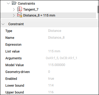
Menu kontekstowe Wiązań zawiera dodatkowe narzędzia:
- Włączony
- Przełącza włączenie ograniczenia.
- Odwróć stronę
- Odwraca stronę ograniczenia (niedostępne dla stałych ograniczeń).
- Zaznacz geometrię
- Wybiera podmioty zaangażowane w ograniczenie.
Menu kontekstowe dla wiązań wymiarowych zawiera dodatkowe narzędzia:
- Oparte na geometrii
- Zaznaczenie tej opcji powoduje, że ograniczenie jest sterowane geometrią.

- Utwórz tabelę projektową
- Tworzy tabelę projektową do sterowania parametrami bloku parametrycznego (patrz panel Menadżer Parametrów).
Menu kontekstowe dla argumentów wiązań zawiera dodatkowe narzędzia:
- Odwróć
- Odwraca kierunek.
- Zastąp...
- Zastępuje bieżący argument innym (patrz polecenie MBWIĄZANIA3D).
- WYKlucz
- Wyklucza bieżący argument.
Właściwości
Wyświetla właściwości wybranych elementów. Jeśli w drzewie zaznaczono kilka węzłów, sekcja Właściwości wyświetla właściwości wszystkich zaznaczonych węzłów. Zmiana właściwości modyfikuje wszystkie wybrane węzły.
Zmień właściwość, klikając pole numeryczne, aby edytować jego wartość lub wybierając inną opcję z listy rozwijanej, która jest otwierana po naciśnięciu strzałki w dół po prawej stronie pola.
Najważniejsze właściwości bloku mechanicznego to:
- Typ rozszerzenia: definiuje typ rozszerzenia dla bloku mechanicznego.
- Podzielny: określa, czy blok mechaniczny jest podzielny.
- Składnik standardowy: określa, czy blok mechaniczny jest składnikiem standardowym.
- Status BOM: definiuje status BOM.
- Materiał: określa materiał.Uwaga: Kliknij przycisk przeglądania (
 ), aby otworzyć okno dialogowe Materiały fizyczne.
 - Właściwości niestandardowe: wyświetla właściwości niestandardowe.Uwaga:
- Kliknij przycisk przeglądania (
 ), aby otworzyć okno dialogowe Właściwości mechaniczne.
 - Kliknij przycisk Wyczyść materiał, aby usunąć materiał.
- Kliknij przycisk przeglądania (
- Preferowany kierunek: wskazuje kierunek dla widoków eksplodowanych, który jest ustawiany za pomocą polecenia BMKONFIGURACJAROZBICIA.


