Modyfikowanie Wywinięć
BricsCAD zapewnia kilka narzędzi do modyfikacji kołnierzy w częściach blaszanych. Narzędzia te mogą być konsekwentnie stosowane do każdej części - niezależnie od jej historii projektowej. W tym artykule korzystamy z narzędzi Bezpośrednie modelowanie i określonych narzędzi do obróbki blachy. Prawie wszystkie narzędzia do modelowania bryłowego mają zastosowanie do części blaszanych, zachowując inteligencję projektową zapewnianą przez Funkcje Arkusza Blachy.
Zmiana rozmiaru i kształtu wywinięcia
Na danym prostym modelu zastosujemy kilka operacji Bezpośrednie modelowanie, aby zmodyfikować kształt jego kołnierzy.
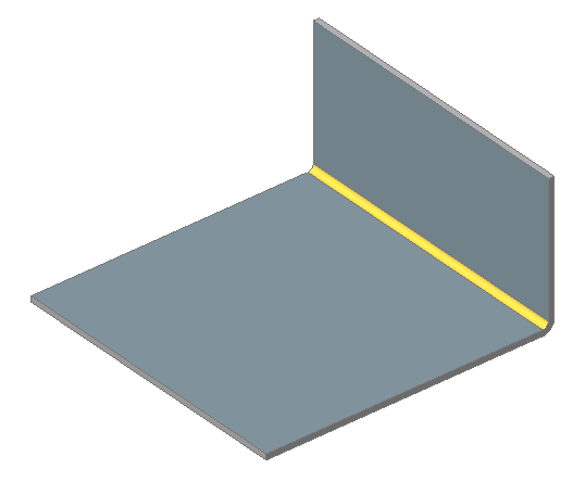
Rozciąganie wywinięć
- Najedź kursorem na powierzchnię grubości, a następnie wybierz Wciśnij/Wyciągnij w grupie poleceń Model w menu Quad.

- Przeciągnij powierzchnie, a następnie kliknij prawym przyciskiem myszy.
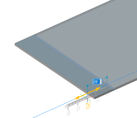 Zmiany zostaną zastosowane do części, kołnierz zostanie rozciągnięty na określoną odległość.
Aby obrócić grubość powierzchni
- Najedź kursorem na twarz i wybierz Obróć w grupie poleceń Model w menu Quad.
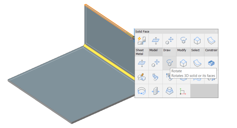
- Określ oś obrotu, punkt bazowy i kąt (więcej informacji można znaleźć w sekcji MBOBRÓĆ w dokumencie Opis Poleceń):
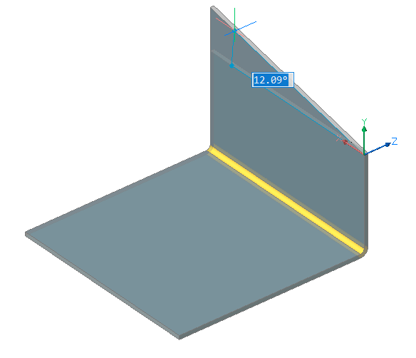
- Zaokrąglij ostre krawędzie.Najedź kursorem na krawędź grubości i wybierz Krawędzie tej samej długości (
 ) z grupy poleceń Wybierz w menu Quad.
- Naciśnij Enter. Wybierane są krawędzie o tej samej długości.
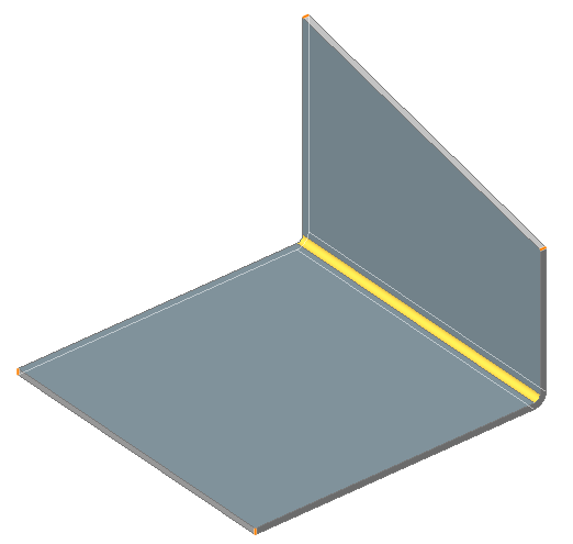
- Wybierz Zaokrągl w grupie poleceń Model w menu Quad.
- Określ żądany promień zaokrąglenia:
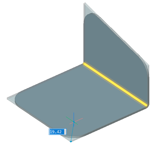
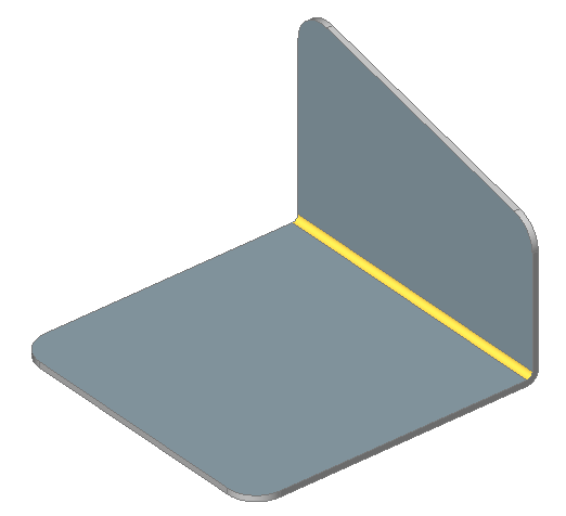
Wykonywanie otworu w wywinięciu
- Utwórz 4 okręgi, jak pokazano na obrazku poniżej. Użyj przyciągania do środka jednostki, aby zdefiniować punkty środkowe.
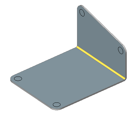
- Wybierz kręgi.
- Wybierz Wyciągnięcie bryły w grupie poleceń Model w menu Quad.
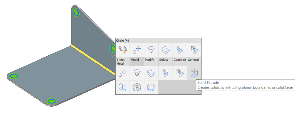
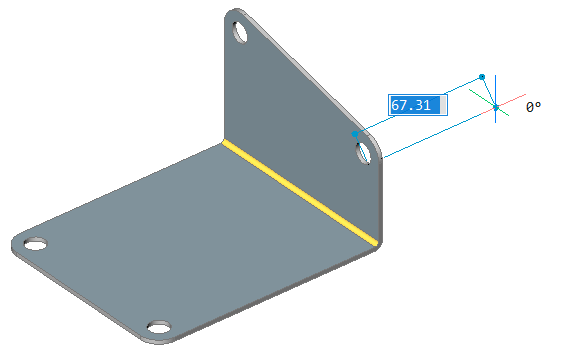
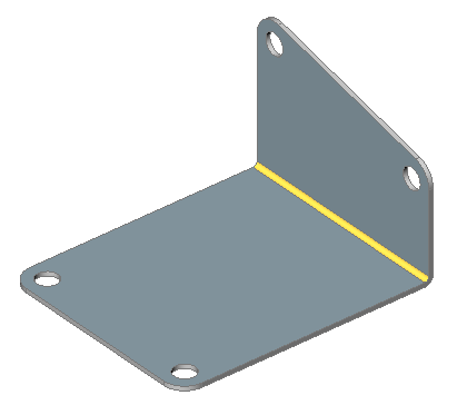
- Przesuń kursor, aby utworzyć otwory.
Przenoszenie wywinięcia
- Wykonaj jedną z następujących czynności:
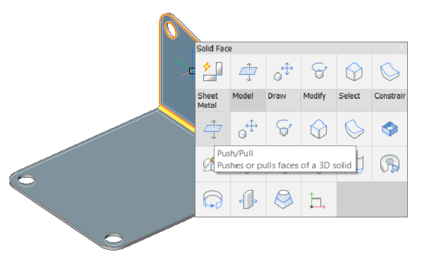
- Kliknij przycisk narzędzia Wciśnij/Wyciągnij (
 ) na pasku narzędzi Modelowanie bezpośrednie.
 - Wybierz Modelowanie bezpośrednie > Wciśnij/Wyciągnij w menu Model.
- Wybierz Wciśnij/Wyciągnij (
 ) w panelu Edycja zakładki Arkusz Blachy na wstążce.
 - Uruchom polecenie MBWCIŚNIJWYCIĄGNIJ dla danej powierzchni.
- Najedź kursorem na twarz, którą chcesz przesunąć i wybierz Wciśnij/Wyciągnij w grupie poleceń Model w menu Quad.
- Kliknij przycisk narzędzia Wciśnij/Wyciągnij (
- Wybierz nową pozycję wywinięcia.Note: Ze względu na obecność Właściwości blachy, grubość części jest zachowana.
Obracanie wywinięcia
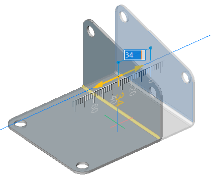
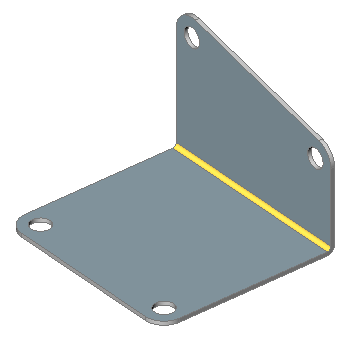
Chociaż możliwe jest obrócenie kołnierza za pomocą polecenia MBOBRÓĆ ( ), zaleca się użycie polecenia ABOBRÓĆWYWINIĘCIE (
 ). (), ponieważ polecenie to automatycznie wybiera oś obrotu zgodnie z założeniami projektowymi części blaszanej.
- Uruchom polecenie ABOBRÓĆWYWINIĘCIE (
 ).Zostanie wyświetlony monit: Wybierz powierzchnię kołnierza do obrócenia:Powierzchnie wywinięcia pod kursorem zostaną podświetlone.
 - Kliknij, aby wybrać powierzchnię kołnierza.Kołnierz obraca się dynamicznie.Wymiar dynamiczny wyświetla bieżący kąt w odniesieniu do kołnierza bazowego.
- Wykonaj jedną z następujących czynności:
- Wybierz punkt.
- Wpisz wartość w polu wymiaru dynamicznego.
- Naciśnij przycisk TAB, a następnie określ bezwzględny kąt obrotu w polu wymiaru dynamicznego.
Dzielenie wywinięcia
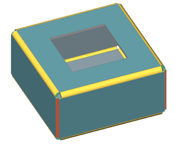
W niektórych przypadkach kołnierze są lepiej podzielone, aby zminimalizować zużycie materiału, na przykład, gdy kołnierz ma duży otwór, jak pokazano na poniższym obrazku:
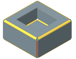
- Uruchom polecenie ABPODZIEL (
 ).Zostanie wyświetlony monit: Wybierz linie lub krawędzie do podziału kołnierza lub [Inteligentny Podział/rysuj Nową linię/Opcje wyboru (?)] <Rysuj nową linię>:
 - Naciśnij Enter, aby zaakceptować opcję domyślną.Pasek poleceń wyświetli: Punkt początkowy linii:
- Najedź kursorem na twarz, którą chcesz podzielić (upewnij się, że opcja Dynamiczny LUW (DLUW) jest włączona). Twarz rozświetla się.
- Określ punkt początkowy linii.Pasek poleceń wyświetli: Koniec linii:
- Określa punkt końcowy linii:Zostanie wyświetlony monit: Zrób podział Środek/Lewo/Prawo/<Akceptuj model>:
- Aby dostosować położenie cięcia względem linii, wykonaj jedną z następujących czynności:
- Naciśnij przycisk CTRL, aby przełączyć opcje Środek/Lewo/Prawo.Jeśli WSKAZÓWKI jest włączone, aktualnie wybrana opcja jest wskazywana w widżecie wskazówek.
- Wybierz Środek , Lewo lub Prawo w menu podpowiedzi.
- Wpisz opcję w wierszu poleceń, a następnie naciśnij Enter.
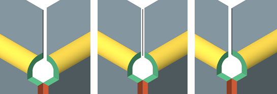 Kołnierz jest przecięty linią: lewą, środkową lub prawą.
- Naciśnij przycisk CTRL, aby przełączyć opcje Środek/Lewo/Prawo.
Inteligentne narzędzia do dzielenia kołnierza
- Inteligentny podział poprzez wybranie pojedynczego wierzchołka w rogu.s
- Podziel gięcie i przekształć część przylegającą do narożnika w złącze.
- Wykonaj jedną z następujących czynności:
- Kliknij narzędzie Inteligentny Podział (
 ) na karcie wstążki Arkusz Blachy.
 - Wybierz Inteligentny Podział w menu .
- Wpisz ABPODZIEL w wierszu poleceń.
Zostanie wyświetlony monit: Wybierz linie lub krawędzie do podziału kołnierza lub [Inteligentny Podział/rysuj Nową linię/Opcje wyboru (?)] <Rysuj nową linię>:
Wybierz opcję Inteligentny Podział.
- Kliknij narzędzie Inteligentny Podział (
- Zostanie wyświetlony monit: Wybierz punkt na obrzeżu kołnierza lub wyciągniętego gięcia dla inteligentnego podziału lub [Propaguj wywinięcie/Propaguj wierzchołek] <Propaguj wierzchołek>:
- Wybierz narożny wierzchołek lub przyciągnij do punktu na krawędzi kołnierza, który chcesz podzielić:
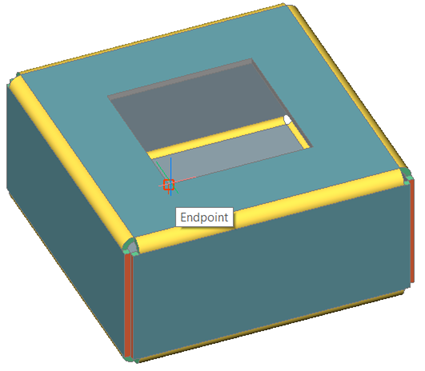 Zostanie wyświetlony monit: Dokonaj podziału [Środek/Lewo/Prawo/Akceptuj]: <Akceptuj>
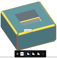
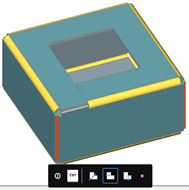
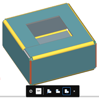
- Wykonaj jedną z następujących czynności:
- Naciśnij Enter, aby zaakceptować podział.
- Naciśnij kilkakrotnie przycisk CTRL.Jeśli WSKAZÓWKI jest włączone, aktualnie wybrana opcja jest wskazywana w widżecie wskazówek.Kołnierz jest przecinany linią przechodzącą przez określony punkt. Zakręt jest częściowo przekształcony w złącze:
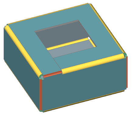 W przypadku opcji Środek, jeśli włączona jest opcja Inteligentne funkcje, wycięcia narożnika przylegające do podziału zostaną przekształcone w wycięciu na gięciu.
Note: Konwersja części zagięcia w skrzyżowanie nie jest związana z trybem Inteligentny Podział.
Gięcie Wywinięcia
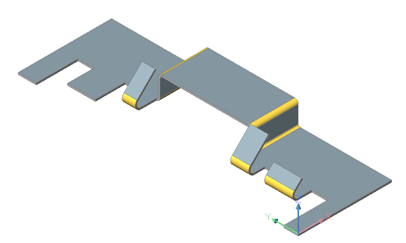
Polecenie ABWYWINIĘTEGIĘCIE wygina jeden lub więcej kołnierzy za pomocą linii. Można najpierw narysować linię, a następnie uruchomić polecenie lub użyć opcji Nowa linia polecenia.
Aby zginać wiele kołnierzy jednocześnie
- Uruchom polecenie ABWYWINIĘTEGIĘCIE.Zostanie wyświetlony monit: Wybierz powierzchnię wywinięcia [opcje wyboru (?)]:
- Wybierz kołnierz, który chcesz zgiąć.Pasek poleceń wyświetli: Wybierz linię lub krawędź do zagięcia bryły lub narysuj [Nowa linia] <Nowa linia>:
- Wykonaj jedną z następujących czynności:
- Wybierz linię, która zachodzi na zagięty kołnierz (kołnierze).
- Wybierz opcję Nowa linia.Zostanie wyświetlony monit o narysowanie linii na kołnierzu(-ach), które mają zostać wygięte.
Zostanie wyświetlony monit:Wybierz pozycję wywinięcia [Kąt/Promień/Przełącz strony/Zmień zakres gięcia/Akceptuj] <Akceptuj>: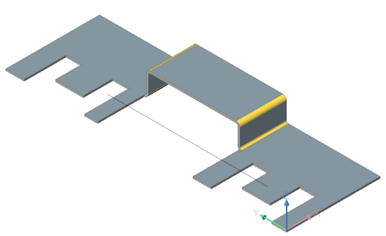 Wybierz punkt z boku linii, którą chcesz przesunąć.Wybrana część jest wyginana dynamicznie.
 - (opcjonalnie) Wpisz wartość, aby zdefiniować kąt zgięcia, używając domyślnego promienia zgięcia.
- (opcja) Wybierz opcję Promień.
Zostanie wyświetlony monit: Wprowadź promień gięcia [Wstecz] <Wstecz>:
Wpisz wartość, aby zastąpić domyślny promień gięcia i naciśnij Enter.
- (opcja) Wybierz opcję Kąt.
Zostanie wyświetlony monit: Wprowadź kąt zgięcia [Wstecz] <Wstecz>:
Wpisz wartość, aby zdefiniować kąt zgięcia.
Połącz Wywinięcia
Polecenie ABPOŁĄCZWYWINIĘCIE zamyka szczeliny między 2 dowolnie zorientowanymi kołnierzami.
- Uruchom polecenie ABPOŁĄCZWYWINIĘCIE.Zostanie wyświetlony monit: Wybierz płaskie powierzchnie dwóch kołnierzy:Powierzchnie wywinięcia pod kursorem zostaną podświetlone.
- Wybierz grubość ściany pierwszego kołnierza.Pojawi się monit:Obiekty / Podobiekty w zestawie: 1Wybierz płaskie powierzchnie grubości dla dwóch wywinięć:
- Wybierz grubość ściany drugiego kołnierza.Powierzchnie o wybranej grubości są połączone.

