AMWELDSYM command
Creates a welding symbol.

Icon: ![]()
Method
Select the entity to attach the welding symbol and specify the points for its location. The Weld Symbol dialog box opens, where you can customize the weld symbol.
- Istnieją dwa przypadki użycia do aktywacji jednostek mechanicznych:
-
- Podczas tworzenia nowego rysunku zawierającego elementy mechaniczne:
- Ustaw zmienną systemową LOADMECHANICAL2D na ON (1).
- Rozpocznij nowy rysunek przy użyciu szablonu Mechanical2d.
- Podczas otwierania rysunku zawierającego elementy mechaniczne:
- Ustaw zmienną systemową LOADMECHANICAL2D na ON (1).
- Otwórz istniejący rysunek ACM i rozpocznij tworzenie symboli specjalnych.
- Podczas tworzenia nowego rysunku zawierającego elementy mechaniczne:
Note: Wymiary te są zgodne ze starszą aplikacją AutoCAD® Mechanical.
Note: Wymiary zostaną dodane do warstwy AM_5.
Note: Po otwarciu rysunku zawierającego jednostki mechaniczne, wypełnianie innych rysunków danymi związanymi z mechaniką będzie wykonywane na żądanie, w przeciwieństwie do poprzednich wersji. Będzie to możliwe, gdy użytkownik skopiuje elementy związane z mechaniką do czystego rysunku. W przypadku kopiowania elementów niezwiązanych z danymi mechanicznymi czysty rysunek nie zostanie wypełniony danymi mechanicznymi.
Note: Po otwarciu rysunku zawierającego elementy mechaniczne, ale zmienna systemowa LOADMECHANICAL2D jest wyłączona, na pasku stanu wyświetlany jest dymek ostrzegawczy opisujący sytuację i zawierający hiperłącze do natychmiastowego włączenia i załadowania modułów mechanicznych 2d.
After creating the symbol prototype with the AMWELDSYM command, you can configure the exact welding symbol's properties from the Properties panel:
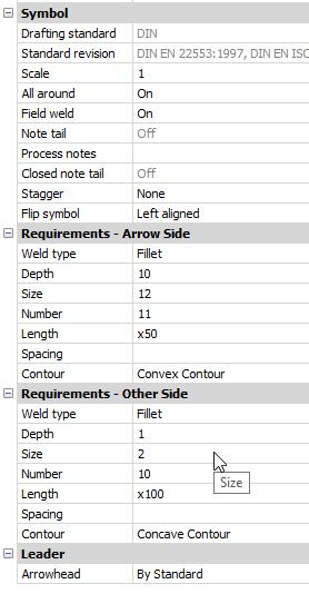
- Symbol
-
- All Around
- Toggles the visibility of the All Around symbol in the welding symbol.
- Field weld
- Toggle the visibility of the Field weld symbol in the welding symbol.
- Note tail
- Displays the state of the note tail.
- Process notes
- Defines the process notes.
- Closed note tail
- Defines the closed note tail.
- Stagger
- Chooses between move and mirrored stagger for intermittent welds on both sides.
- Flip symbol
- Chooses between left and right aligned for weld symbol.
- Requirements - Arrow side
-
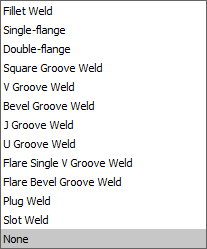
- Weld type
- Defines the weld type from the options below:
-
- Depth
- Defines the groove depth of the weld.
- Size
- Defines the size of the weld.
- Length
- Defines the length of the weld.
- Spacing
- Defines the spacing dimension for intermittent weld.
- Contour
- Defines the shape of the weld.
- Requirements - other side
- Defines the type and dimensions of the weld on the other side.
- Leader
- Defines the default arrowhead type for welding symbols.