AMSURFSYM command
Creates a surface symbol.

Icon: ![]()
Method
Select the object to attach the surface symbol and specify the points for its location.
- Istnieją dwa przypadki użycia do aktywacji jednostek mechanicznych:
-
- Podczas tworzenia nowego rysunku zawierającego elementy mechaniczne:
- Ustaw zmienną systemową LOADMECHANICAL2D na ON (1).
- Rozpocznij nowy rysunek przy użyciu szablonu Mechanical2d.
- Podczas otwierania rysunku zawierającego elementy mechaniczne:
- Ustaw zmienną systemową LOADMECHANICAL2D na ON (1).
- Otwórz istniejący rysunek ACM i rozpocznij tworzenie symboli specjalnych.
- Podczas tworzenia nowego rysunku zawierającego elementy mechaniczne:
Note: Wymiary te są zgodne ze starszą aplikacją AutoCAD® Mechanical.
Note: Wymiary zostaną dodane do warstwy AM_5.
Note: Po otwarciu rysunku zawierającego jednostki mechaniczne, wypełnianie innych rysunków danymi związanymi z mechaniką będzie wykonywane na żądanie, w przeciwieństwie do poprzednich wersji. Będzie to możliwe, gdy użytkownik skopiuje elementy związane z mechaniką do czystego rysunku. W przypadku kopiowania elementów niezwiązanych z danymi mechanicznymi czysty rysunek nie zostanie wypełniony danymi mechanicznymi.
Note: Po otwarciu rysunku zawierającego elementy mechaniczne, ale zmienna systemowa LOADMECHANICAL2D jest wyłączona, na pasku stanu wyświetlany jest dymek ostrzegawczy opisujący sytuację i zawierający hiperłącze do natychmiastowego włączenia i załadowania modułów mechanicznych 2d.
After creating the symbol prototype with the AMSURFSYM command, you can configure the exact surface symbol's properties in the Properties panel:
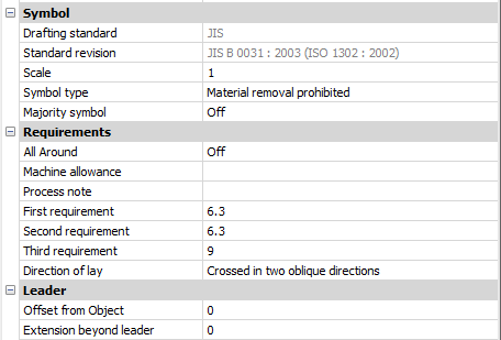
Note: The surface symbol properties depend on the used standard.
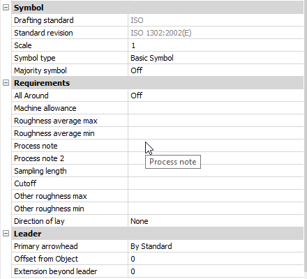
Symbol
- Symbol type
- Choose one of the following:
-
- Basic symbol

- Material removal required

- Material removal prohibited

- Basic symbol
- Majority symbol
- Indicates the common state of all surfaces using a single collective indication symbol.
Requirements
- All Around
- Toggles the visibility of the All Around surface texture in the symbol.
- Machine allowance
- Specifies the machining allowance for the surface.
- Process note
- Defines the process requirements for the surface.
- First requirement
- Defines the first requirement for the surface.
- Second requirement
- Defines the second requirement for the surface.
- Third requirement
- Defines the third requirement for the surface.
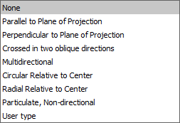
- Direction of lay
-
Sets the direction of lay for the surface.
-
- Roughness average max
- Defines the maximum roughness average for the surface.
- Roughness average min
- Defines the minimum roughness average for the surface.
- Process note2
- Defines the process requirements for the surface.
- Sampling length
- Defines the sampling length required for the surface.
- Other roughness max
- Defines the maximum other roughness for the surface.
- Other roughness min
- Defines the minimum other roughness for the surface.
Leader
- Offset from Object
- Specifies the distance between the extension line’s start point and the attached object.
- Extension beyond leader
- Specifies the distance between the symbol’s start point and the surface extension line’s end point.