Okno dialogowe Styl symbolu
Okno dialogowe Styl symbolu umożliwia zdefiniowanie nowego stylu symbolu. Otwiera się za pomocą panelu Civil Explorer Ustawienia.
- Informacje
- Symbol
- Ekran
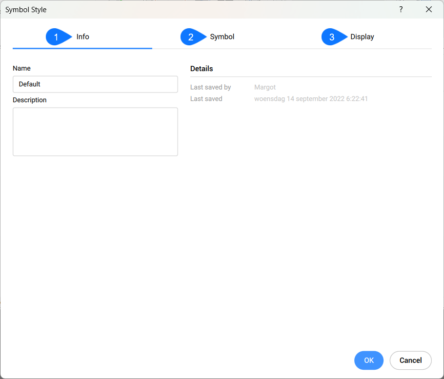
Informacje
Określa ogólne informacje o wybranym stylu symbolu.
- Nazwa
- Opis
- Detale
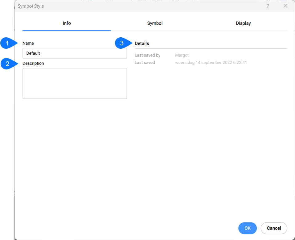
- Nazwa
-
Ustawia i wyświetla nazwę stylu symbolu.
- Opis
-
Ustawia i wyświetla opis stylu symbolu.
- Detale
-
Wyświetla ostatnio zapisane przez i datę ostatniego zapisu.
Symbol
Zakładka Symbol umożliwia ustawienie stylu symbolu.
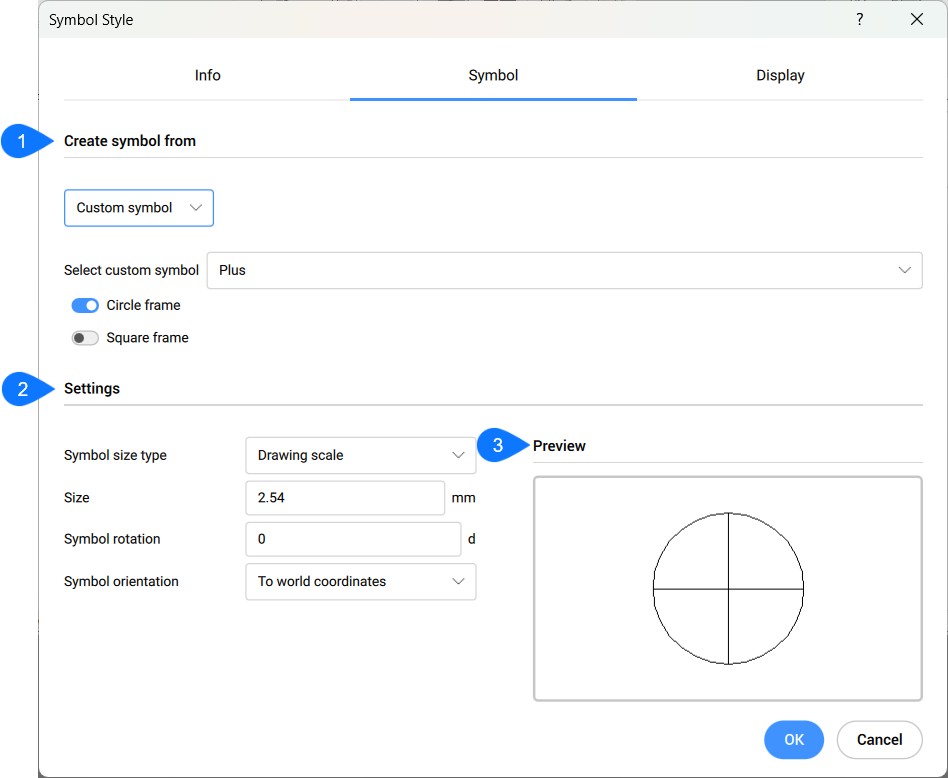
- Utwórz symbol z
- Ustawienie
- Podgląd
- Utwórz symbol z
- Określa typ symbolu używany do tworzenia stylu symbolu. Z rozwijanego menu można wybrać kilka opcji.
-
- Obiekt punktowy
- Używa obiektu punktowego jako podstawy stylu symbolu.
-
- Symbol niestandardowy
- Umożliwia utworzenie stylu symbolu, zaczynając od jednego z poniższych symboli niestandardowych:
- Żaden
- Kropka
- Plus
- Znak X
- Linia
-
- BLok
-
Umożliwia utworzenie stylu symbolu z bloku na rysunku.
-
- Ustawienia
-
Umożliwia określenie konkretnych cech w zależności od wybranego typu symbolu.
Niestandardowe ustawienia symboli
- Podgląd
- Wyświetla podgląd określonego stylu symbolu.
Karta wyświetlania
Umożliwia określenie sposobu wyświetlania wszystkich elementów symbolu.
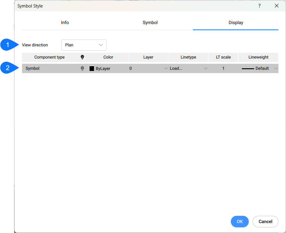
- Kierunek widoku
- Charakterystyka typu komponentu
- Kierunek widoku
- Określa, dla którego kierunku widoku modyfikowana jest charakterystyka wyświetlania. Dostępne są dwie opcje:
- Plan
- Model
- Charakterystyka typu komponentu
- Określa charakterystykę wyświetlania elementu symbolu.
- Kolor
-
Określa kolor elementu symbolu.
- WArstwa
-
Określa warstwę komponentu symbolu.
- Rodzaj linii
-
Określa rodzaj linii elementu symbolu.
- Skala Rodzaju Linii
-
Określa skalę typu linii elementu symbolu.
- SzerokośćLinii
-
Określa grubość linii elementu symbolu.