Panel Eksploratora Civil
Ikona: 
Opis
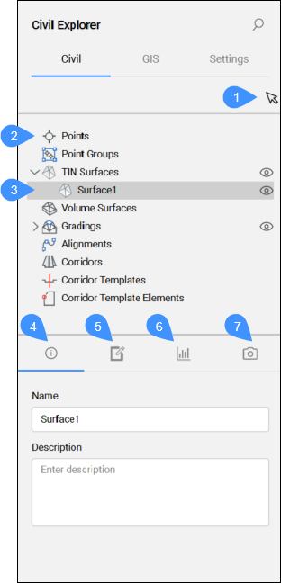
Civil Eksplorator to główny panel do zarządzania obiektami Civil i uzyskiwania do nich dostępu. Obiekty są rozmieszczone w widoku drzewa i pogrupowane według typu obiektu.
Za pomocą tego panelu można uzyskać dostęp do ustawień i właściwości podmiotów Civil oraz edytować istniejące i dodawać nowe podmioty i ich komponenty.
Panel jest podzielony na dwie części. Górna część z listą podmiotów w widoku drzewa, a dolna część z dodatkowymi właściwościami, w zależności od wyboru w widoku drzewa.
Panel Eksplorator Civil jest podstawowym panelem do projektowania Civil. W obszarze roboczym Civil kliknij ikonę Eksplorator Civil na wstążce w zakładce Narzędzia Główne, aby włączyć/wyłączyć panel.

Panel Civil Eksplorator zawiera trzy karty: Civil, GIS i Ustawienia.
Karta Civil
Zakładka Civil umożliwia zarządzanie i dostęp do jednostek Civil w bieżącym rysunku.
- Wybierz obiekt Civil
- - Typ obiektu Civil 3D
- Wybierz typ obiektu Civil.
- Informacje
- Definicje
- Statystyki
- Style Wizualne
- Wybierz obiekt Civil
- Wskaż obiekt Ciągu Civil na rysunku.
- - Typ obiektu Civil 3D
- Obiekty Civil są ułożone w widoku drzewa. W górnej części struktury drzewa wymienione są wszystkie typy obiektów. Na niższym poziomie, pod każdym typem obiektów, zbierane są obiekty, które już istnieją na rysunku.
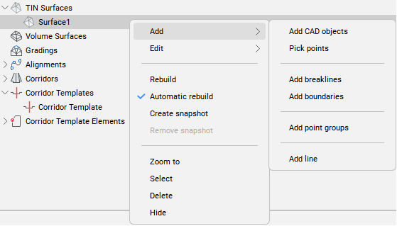
Kliknij prawym przyciskiem myszy typ obiektu Civil, aby otworzyć menu kontekstowe zawierające opcję Utwórz, która uruchamia określone polecenia w celu utworzenia wybranego obiektu Civil.
Menu po kliknięciu prawym przyciskiem myszy zawiera również opcję Ukryj, która umożliwia przełączanie widoczności dla każdego typu obiektu Civil.
- Wybierz typ obiektu Civil.
- Podświetla wybrany obiekt Civil w widoku drzewa.
- Kliknięcie jednostki prawym przyciskiem myszy otwiera menu kontekstowe zawierające opcje Edycji specyficzne dla jednostki, a także opcje wspólne dla wszystkich jednostek, takie jak Powiększ, Zaznacz, Usuń i Ukryj.
Dostępne opcje edycji zależą od typu podmiotu:
- Punkty
- Istniejące punkty nie są wyświetlane na karcie Civil w Civil Eksplorator. Nowe punkty Civil można tworzyć, klikając punkty prawym przyciskiem myszy i wybierając opcję Utwórz z menu kontekstowego.
- Grupy Punktów
- Wybierz opcję Utwórz z menu kontekstowego, aby otworzyć okno dialogowe Grupa punktów.
Menu kontekstowe dla zdefiniowanych grup punktów zawiera opcje Edytor punktów Civil, Edytuj grupę punktów, Powiększ do, Wybierz, Przesuń do, Usuń i Ukryj.
Uwaga: Kliknij dwukrotnie węzeł Grupy Punktów, aby otworzyć okno dialogowe Edytor Punktów Civil.Uwaga: Edytuj grupę punktów otwiera okno dialogowe Grupa punktów.
- Powierzchnie TIN
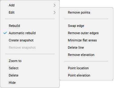
- Korzystając z Civil Eksplorator, można edytować istniejące i dodawać nowe elementy do istniejących powierzchni TIN.Uwaga: Wszystkie opcje opcji Dodaj i Edytuj w menu kontekstowym są również dostępne w poleceniu TINEDYTUJ.
-
-
- Powierzchnie Objętościowe
- Opcje Przybliż do, Wybierz, Usuń i Ukryj są dostępne dla powierzchni objętościowych.
- Skarpy
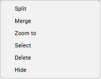
- Oprócz typowych opcji, dla klasyfikacji dostępne są opcje Podziału i Scalania.Uwaga: Opcje tej Edycji są również dostępne w poleceniu SKARPAEDYCJA.
-
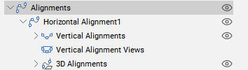
- Wyrównanie
- Typ jednostki Wyrównania gromadzi istniejące wyrównania poziome i powiązane z nimi wyrównania pionowe, wyrównania 3D i widoki wyrównania pionowego.
-
-

- Korytarze
- Kliknięcie prawym przyciskiem myszy istniejącego korytarza udostępnia wszystkie opcje Edycji dostępne w poleceniu KORYTARZEDYCJA. Oprócz opcji Edycji dostępne są także opcje Przybliż do, Wybierz, Usuń i Ukryj.

- Szablony Korytarza
- Do wyboru są opcje Dodaj element szablonu, Powiększ do, Wybierz, Usuń i Ukryj.Uwaga: Opcja Dodaj element szablonu jest również dostępna w poleceniu SZABLONKORYTARZA.
-

- Elementy Szablonu Korytarza
- Kliknięcie prawym przyciskiem myszy Wyrównanie poziome udostępnia wszystkie opcje edycji dostępne w poleceniu ELEMENTSZABLONUKORYTARZAEDYCJA. Oprócz opcji Edycji, dostępne są również typowe opcje, takie jak Przybliż do, Wybierz, Usuń i Ukryj.
-

- Informacje
- Wyświetla informacje o wybranym obiekcie Civil (nazwa i opis). Oba mogą być edytowane.
- Definicje
- Pokazuje komponenty (dane źródłowe), z których zbudowano powierzchnię TIN, zastosowane operacje edycji oraz chronologiczną kolejność dodawania definicji. Widok można przełączać, wybierając zakładkę Według komponentu lub Według kroku.
-

-
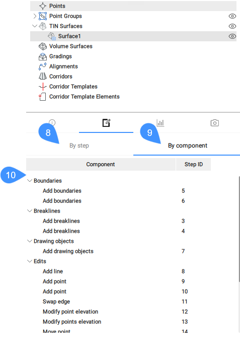
8. Krok po kroku
9. Według komponentu
10. Lista wszystkich definicji/składników użytych do utworzenia powierzchni TIN
- Statystyki
- Zakładka Statystyki wyświetla statystyki dla wybranej powierzchni TIN (liczba punktów i trójkątów, minimalna i maksymalna wysokość, obszar 2D i 3D).
-

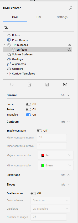
- Style wizualne
- Zakładka Style wizualne umożliwia ustawienie stylów wizualnych dla powierzchni TIN:
- ogólny styl wizualny - wybierz, które elementy powierzchni TIN mają być wyświetlane (obramowanie, punkty, trójkąty).
- styl wizualny dla konturów.
- styl wizualny dla analizy elewacji.
- styl wizualny dla analizy nachylenia.
Zakładka GIS
Karta GIS zawiera listę wszystkich warstw GIS na rysunku i pomaga zarządzać ich widocznością.
Jeśli na rysunku nie ma warstwy GIS, na karcie GIS dostępne są trzy opcje:
- Importuj warstwy GIS
- Utwórz warstwę GIS
- Konwertuj z Danych Obiektu

|
|
- Importuj warstwy GIS
- Umożliwia importowanie wybranych plików Shape. Po wybraniu plików Shape otworzy się okno dialogowe importu GIS. Sprawdź polecenie GISIMPORT, aby uzyskać szczegółowy opis okna dialogowego importu GIS.
- Utwórz nową warstwę GIS
- Umożliwia utworzenie nowej warstwy GIS. Po uruchomieniu polecenia otwarte zostanie okno dialogowe Utwórz nową warstwę GIS:
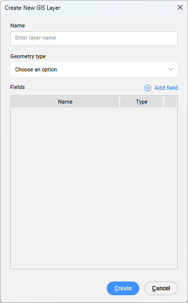
- Nazwa
- Umożliwia wprowadzenie nazwy warstwy.
- Typ geometrii
- Umożliwia wybór typu granicy.
- Punkt
- Linia
- Wielobok
- Dodaj pole
- Dodaje nowe pole warstwy GIS.
Kliknięcie przycisku Dodaj pole powoduje dodanie nowego pola do listy pól, z domyślną nazwą NowePole i domyślnym typem Ciąg. Pola Nazwa i Typ można edytować.
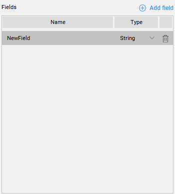
Dostępne są następujące typy:
- Struna
- Rzeczywista
- Całkowita
Kliknij ikonę kosza w tabeli, aby usunąć pola.
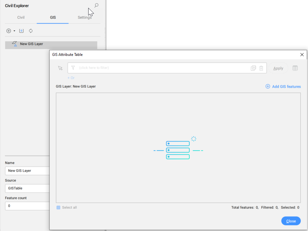
Po pierwszym otwarciu tabeli nowo utworzonej warstwy GIS jest ona pusta. Zawiera tylko kolumny z nazwami.
- Konwertuj z Danych Obiektu
- Konwertuje dane obiektów w bieżącym rysunku z Autodesk Map3D lub Civil 3D na dane BricsCAD GIS.
- Widok drzewa
- Wyświetla listę wszystkich dodanych pól warstwy GIS.Uwaga: Grupy i warstwy GIS można zmieniać za pomocą metody "przeciągnij i upuść".
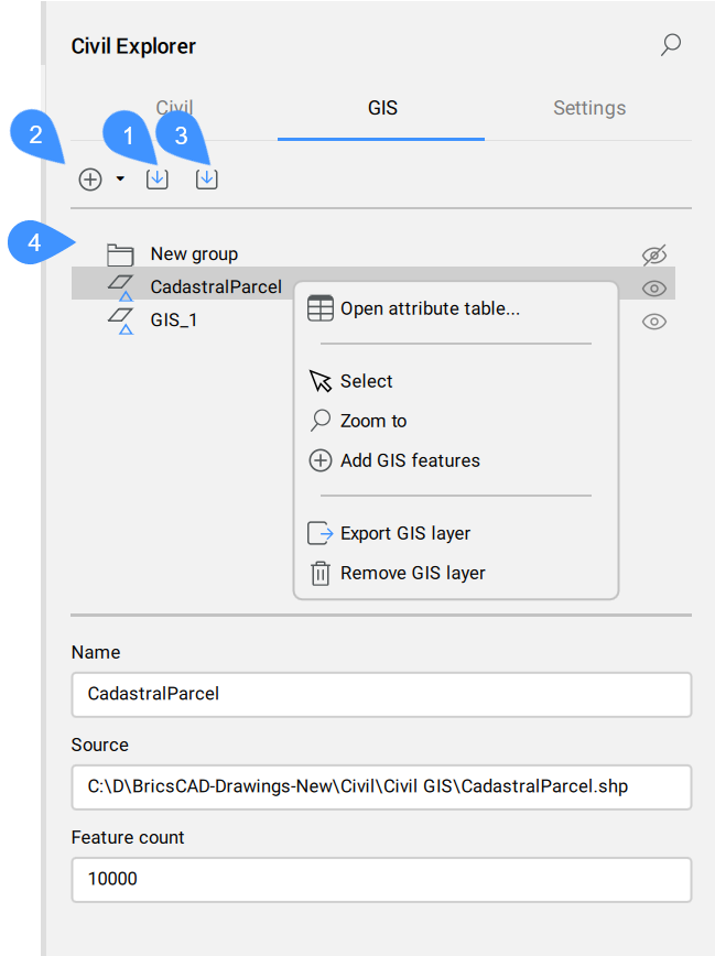
Po kliknięciu prawym przyciskiem myszy warstwy GIS otwiera się następujące menu kontekstowe:
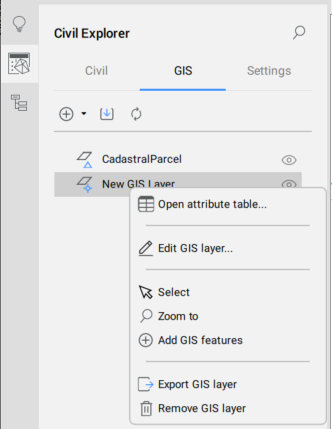
- Otwarta tabela atrybutów...
- Otwiera okno dialogowe Tabela atrybutów GIS.
- Edytuj warstwę GIS
- Otwiera okno dialogowe Edytuj warstwę GIS.
- Wybierz
- Wybiera warstwę GIS.
- Przybliż do
- Powiększa warstwę GIS.
- Dodaj funkcje GIS
- Dodaje jednostki do warstwy GIS. Zostanie wyświetlony wiersz polecenia umożliwiający wybranie elementów liniowych na rysunku. Zostanie otwarte okno dialogowe Tabela atrybutów GIS , w którym nowe funkcje GIS zostaną dodane na końcu tabeli. Tabela zostanie przewinięta do tej lokalizacji.
- Eksportuj warstwę GIS
- Eksportuj warstwę GIS
- Usuń warstwę GIS
- Usuń warstwę GIS
Po kliknięciu arkusza prawym przyciskiem myszy wyświetlane jest menu kontekstowe:

- Zmień nazwę grupy
- Zmienia nazwy grup.
- Dodaj podgrupę
- Dodaj podgrupę
- Usuń grupę
- Usuń grupę
Karta Ustawienia
Zakładka Ustawienia zarządza stylami i formatami podmiotów Civil.
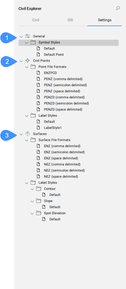
- Ogólne
- Punkty Civil
- Powierzchnie
- Ogólne
- Definiuje ogólne style symboli dla podmiotów Civil.
- Styl symbolu
- Wyświetla predefiniowane i niestandardowe style symboli. Styl symbolu można utworzyć, edytować, skopiować lub usunąć. Kliknij odpowiednią opcję z menu kontekstowego, aby otworzyć okno dialogowe Styl symbolu.
- Punkty Civil
- Wyświetla listę dostępnych stylów etykiet dla Punktów Civil.
- Powierzchnie
- Definiuje formaty plików powierzchni i style etykiet dla konturu, nachylenia i wysokości punktowej.