Configurações do Inspetor de Montagem caixa de diálogo
A caixa de diálogo Configurações do Inspetor de Montagem permite criar mapeamentos de ferramentas.
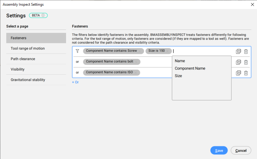
Fixações
Existem ferramentas de pré-configuração de Fixações:
Define filtros para identificar fixadores na montagem. Para a amplitude de movimento da ferramenta, apenas os fixadores são considerados (se também estiverem mapeados para uma ferramenta). Fixadores não são considerados para os critérios de liberação do caminho e visibilidade.

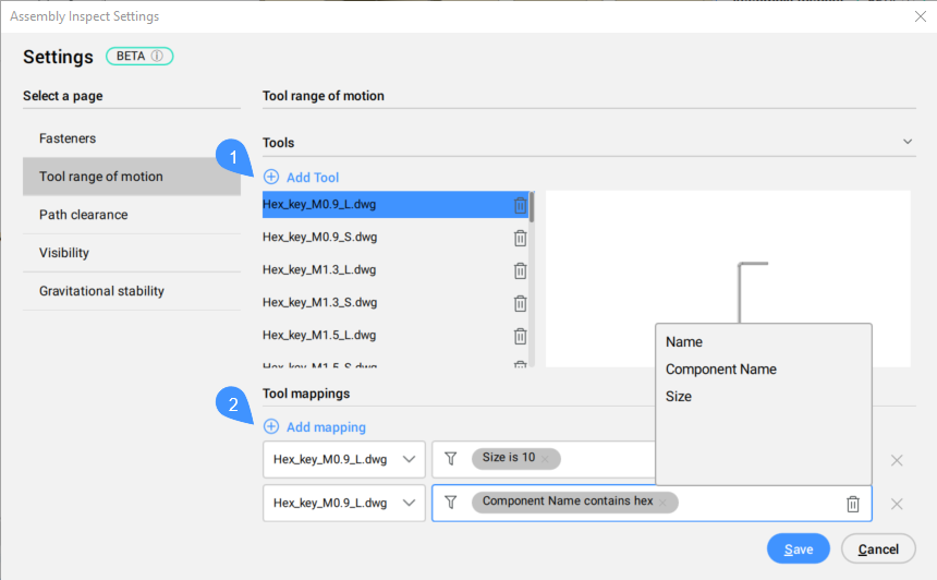
Amplitude de movimento da ferramenta

- Adicionar Ferramenta
- Mapeamentos de ferramentas
- Adicionar Ferramenta
- Adiciona um desenho com uma ferramenta.
- Mapeamentos de ferramentas
- Adiciona mapeamento à ferramenta selecionada.
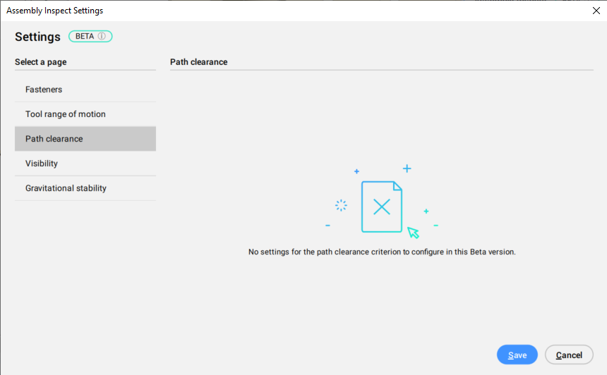
Liberação do caminho

Visibilidade
Define os pontos de vista do operador com base na distância ao centro da montagem, e no ângulo no plano XY. Quatro pontos de vista são definidos por padrão, mas você pode adicionar outros pressionando o botão Adic. ponto de vista. As imagens no painel mostram o que está visível e o que está bloqueado, de uma forma colorida e compreensível. Para cada imagem, um gráfico da câmera é exibido no Model Space, esclarecendo de qual ponto de vista a imagem foi tomada.

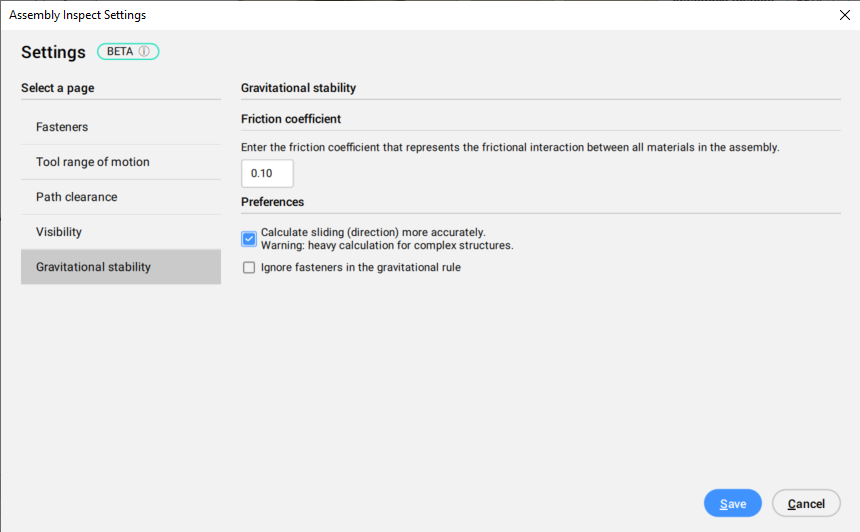
Estabilidade gravitacional
Verifica a estabilidade de três maneiras: cair, deslizar, e inclinar. Se as peças estiverem caindo, o deslizamento e a inclinação não serão mais considerados. Os resultados parciais das três verificações são mostrados, bem como setas temporárias no Model Space. Todas as peças de uma etapa são consideradas separadamente, tanto no cálculo quanto na apresentação dos resultados.


