PUNKTWOLKENPROFILSWEEP Befehl
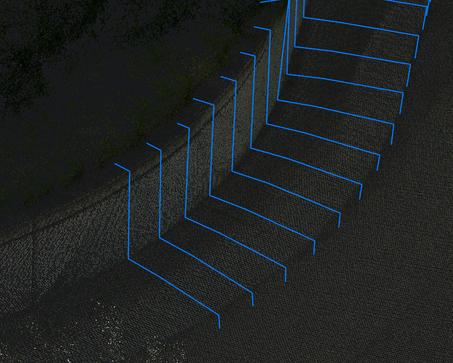
Rekonstruiert ein lineares Feature in einer Punktwolke.

Symbol: 
Beschreibung
Rekonstruiert ein lineares Feature in einer Punktwolke, indem eine Reihe von Profil-Schlüsselpunkten in aufeinanderfolgenden Querschnitten der Punktwolke verbunden wird. Die Erkennung des Profils im nächsten Querschnitt kann automatisch oder manuell erfolgen.
Methode
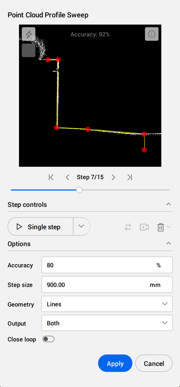
Starten Sie den Befehl, um das Befehlskontext-Panel Punktwolken Profil Sweep zu öffnen.
Anmerkung: Um die Auswahl relevanter Punkte in der Punktwolke zu verbessern, aktivieren Sie den Objektfang Punktwolke Nächster Punkt (siehe den Artikel PWNÄCHSTE Befehl).
Im Modelbereich:
- Klicken Sie auf einen Punkt in der Punktwolke in der Nähe der linearen Kante, um die Startposition zu definieren.
- Klicken Sie auf einen zweiten Punkt in der Punktwolke, um die Richtung der linearen Kante anzunähern. Diese Richtung wird in den nächsten Schritten verfeinert.
- Klicken Sie auf einen beliebigen Griffpunkt, ziehen Sie ihn und klicken Sie erneut, um die Position, Größe oder Richtung des Profilschnitts zu ändern.
Im Befehlskontext-Panel:
- Klicken Sie in die Schnittvorschau, um Leitpunkte hinzuzufügen oder zu bearbeiten.
- Stellen Sie die Intervalleinstellungen ein.
- Starten oder pausieren Sie den Intervallmodus.
- Wählen Sie das gewünschte Ausgabeformat.
- Klicken Sie auf Akzeptieren, um die Profilobjekte gemäß der Schritt-für-Schritt-Vorschau zu erstellen, oder klicken Sie auf Abbrechen, um den Befehl zu beenden.
Optionen innerhalb des Befehlskontext-Panels
- Profilvorschau
- Ermöglicht das Hinzufügen von Punkten zur Definition des Intervallprofils.
- Klicken Sie mit der linken Maustaste, um Leitpunkte hinzuzufügen.
- Klicken Sie mit der rechten Maustaste, um Leitpunkte zu entfernen.
- Klicken Sie auf einen Leitpunkt, halten Sie die Maustaste gedrückt und bewegen Sie die Maus, um ihn neu zu positionieren.
- Verwenden Sie das Scrollrad, um hinein- oder herauszuzoomen.
- Um zu schwenken, halten Sie die mittlere Maustaste gedrückt.
- Verwenden Sie den Schieberegler oder die Steuerungstasten, um ein Intervall auszuwählen.
-
 Leitpunkte im Intervallprofil anpassen
- Passt jeden Leitpunkt unabhängig voneinander an, um seine Position im nächsten Intervall bestmöglich anzupassen.
-
 Profil schließen
- Verbindet den ersten und letzten Leitpunkt im Profilschnitt.
- Intervall-Steuerung
-
 Ausführen
- Startet oder setzt den Intervallmodus mit den aktuellen Einstellungen fort.
-
 Pause
Pause- Unterbricht den automatischen Intervallmodus.
-
 Invertieren
- Kehrt die Richtung der Intervalle um.
-
 Kamera ausgerichtet
- Wenn diese Funktion aktiviert ist, wird die Kamera an der Bewegung ausgerichtet.
-
 Intervalle entfernen
- Entfernt die angegebenen Intervalle.
- Optionen
-
- Genauigkeit
- Legt den Genauigkeitsschwellenwert für den Intervallmodus fest.
Der Intervallmodus wird gestoppt, wenn das Ergebnis der Leitpunkt-Übereinstimmung unter dem gewählten Schwellenwert liegt. Um fortzufahren, passen Sie den Schwellenwert oder die Leitpunkte an oder fügen Sie einen manuellen Intervall hinzu.
-
- Ausgabe
- Legt das Ausgabeformat fest.
-
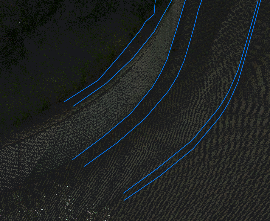
- Leitpunkt-Linien
- Erstellt Geometrien, um Leitpunkte zwischen Intervallprofilen zu verbinden.
-
- Intervall-Linien
- Erstellt Geometrien, um Leitpunkte innerhalb von Intervallprofilen zu verbinden.
-
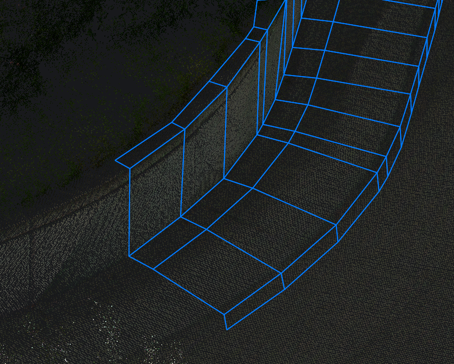
- Beide
- Erstellt Geometrien, um Leitpunkte sowohl innerhalb als auch zwischen Intervallprofilen zu verbinden.
Anmerkung: Die Optionen in der Befehlszeile spiegeln die Optionen im Befehlskontext-Panel wider.