Baugruppenprüfung-Einstellungen Dialog
Im Dialog Baugruppenprüfung-Einstellungen können Sie Werkzeugzuordnungen erstellen.
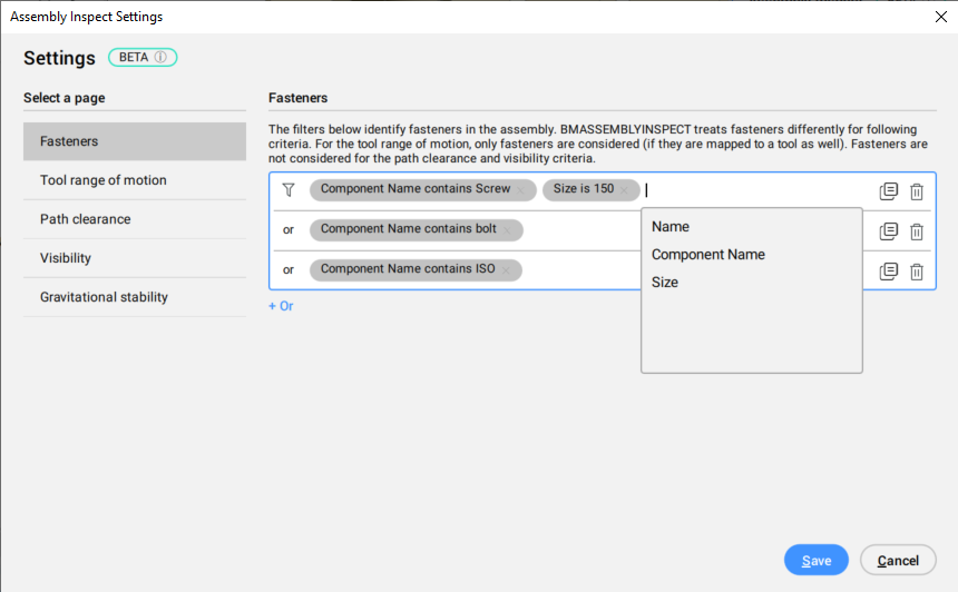
Befestigungselemente
Es gibt ein Vorkonfigurationswerkzeug für Befestigungselemente:
Definiert Filter zum Identifizieren von Befestigungselemente in der Baugruppe. Für den Bewegungsbereich des Werkzeugs werden nur Befestigungselemente berücksichtigt (sofern diese ebenfalls einem Werkzeug zugeordnet sind). Befestigungselemente werden bei den Kriterien Freiraum und Sichtbarkeit nicht berücksichtigt.
Bewegungsbereich des Werkzeugs
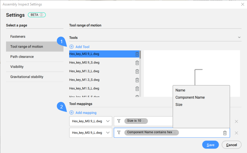
- Werkzeug hinzufügen
- Werkzeugzuordnungen
- Werkzeug hinzufügen
- Fügt eine Zeichnung mit einem Werkzeug hinzu.
- Werkzeugzuordnungen
- Fügt dem ausgewählten Werkzeug eine Zuordnung hinzu.
Freiraum
Sichtbarkeit
Definiert die Ansichtspunkte des Bedieners basierend auf dem Abstand zur Mitte der Baugruppe und dem Winkel in der xy-Ebene. Standardmäßig sind vier Ansichtspunkte definiert, aber Sie können weitere hinzufügen, indem Sie auf die Schaltfläche Ansichtspunkt hinzufügen klicken. Die Bilder im Panel zeigen anhand der Farben deutlich, was sichtbar und was blockiert ist. Für jedes Bild wird ein Kamera-Kegelstumpf im Modelbereich angezeigt, der verdeutlicht, aus welchem Blickwinkel das Bild aufgenommen wurde.

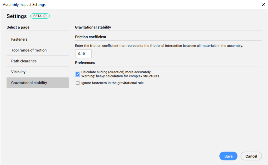
Schwerkraftstabilität
Überprüft die Stabilität auf drei Arten: Fallen, Rutschen und Kippen. Wenn Teile herunterfallen, werden Rutschen und Kippen nicht mehr berücksichtigt. Teilergebnisse für die drei Nachweise werden angezeigt, ebenso wie temporäre Pfeile im Modelbereich. Alle Teile eines Schrittes werden separat betrachtet, sowohl bei der Berechnung als auch bei der Darstellung der Ergebnisse.