


AMDATUMID command
Creates a datum identifier symbol

Icon: 
Method
Select the object to attach the datum identifier symbol and specify the points for its location, then the Datum Identifier dialog box opens. The first leader segment is perpendicular to the attached object.
- Esistono due casi d'uso per attivare le entità meccaniche:
-
- Quando si crea un nuovo disegno che contiene entità meccaniche:
- Impostare la variabile di sistema LOADMECHANICAL2D su ON (1).
- Iniziare un nuovo disegno utilizzando un modello Mechanical2d.
- Quando si apre un disegno che contiene entità meccaniche:
- Impostare la variabile di sistema LOADMECHANICAL2D su ON (1).
- Aprire un disegno ACM esistente e avviate la creazione di simboli speciali.
- Quando si crea un nuovo disegno che contiene entità meccaniche:
Note: Queste quote sono compatibili con l'applicazione legacy AutoCAD® Mechanical.
Note: Le quote verranno aggiunte al layer AM_5.
Note: Dopo l'apertura di un disegno contenente entità meccaniche, il riempimento di altri disegni con dati correlati al meccanico verrà eseguito on-demand in contrasto con le versioni precedenti. Questo sarà possibile quando un utente copia le entità relative al meccanico nel disegno "vanilla". In caso di copia, entità che non sono correlate ai dati meccanici, un disegno "vanilla" non verrà riempito con dati meccanici.
Note: Quando si apre un disegno che contiene entità meccaniche, ma la variabile di sistema LOADMECHANICAL2D è impostata su OFF, sulla barra di stato viene visualizzato un fumetto di avviso che descrive la situazione e fornisce un collegamento ipertestuale per abilitare e caricare immediatamente i moduli 2D di Mechanical.
The Datum Identifier dialog box allows you to set all parameters for the symbol.
Symbol
Specifies the datum identifier symbol characteristics.
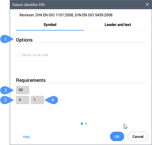
- Options (1)
- Toggles the datum type.
- Identifier (2)
- Defines the identifier which can contain a maximum of two characters.
- Thread note (3)
- Defines the thread notes, which are placed on symbols attached to gears or screw threads. They specify which diameter to use as the datum.
- Datum note (4)
- Defines the reference datum targets which correspond to points on a surface. Generally, it contains a series of datum targets separated by commas (",").
Note: Thread and datum notes are not available for all standards.
Leader and text
Specifies the Leader and text characteristics.
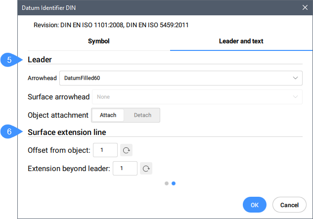
- Leader (5)
- Sets the leader characteristics.
- Arrowhead
- Sets the default leader arrowhead type.
- Surface arrowhead
- Sets the arrowhead for surface indication leaders. Note: This option is only available for the standards which allow surface indicator leaders.
- Object attachment
- Defines if the symbol leader is attached or detached to the object.
- Attach
- Attaches the symbol to the selected object.
- Detach
- Detaches the symbol from the object.
- Surface extension line (6)
- Sets the surface extension line characteristics.
- Offset from object
- Sets the offset from the object.
- Extension beyond leader
- Sets the extension beyond leader.
After creating the datum identifier symbol with the AMDATUMID command, their properties can be changed in the Properties panel:
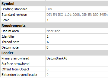
- Symbol
-
- Drafting standard
- Displays the drafting standard.
- Standard revision
- Displays the standard revision.
- Scale
- Sets the note scale.