


AMEDGESYM
Crea un simbolo di spigolo.

Icona: 
Metodo
Selezionare l'oggetto a cui attaccare il simbolo di spigolo e specificare i punti per la sua posizione.
- Esistono due casi d'uso per attivare le entità meccaniche:
-
- Quando si crea un nuovo disegno che contiene entità meccaniche:
- Impostare la variabile di sistema LOADMECHANICAL2D su ON (1).
- Iniziare un nuovo disegno utilizzando un modello Mechanical2d.
- Quando si apre un disegno che contiene entità meccaniche:
- Impostare la variabile di sistema LOADMECHANICAL2D su ON (1).
- Aprire un disegno ACM esistente e avviate la creazione di simboli speciali.
- Quando si crea un nuovo disegno che contiene entità meccaniche:
Note: Queste quote sono compatibili con l'applicazione legacy AutoCAD® Mechanical.
Note: Le quote verranno aggiunte al layer AM_5.
Note: Dopo l'apertura di un disegno contenente entità meccaniche, il riempimento di altri disegni con dati correlati al meccanico verrà eseguito on-demand in contrasto con le versioni precedenti. Questo sarà possibile quando un utente copia le entità relative al meccanico nel disegno "vanilla". In caso di copia, entità che non sono correlate ai dati meccanici, un disegno "vanilla" non verrà riempito con dati meccanici.
Note: Quando si apre un disegno che contiene entità meccaniche, ma la variabile di sistema LOADMECHANICAL2D è impostata su OFF, sulla barra di stato viene visualizzato un fumetto di avviso che descrive la situazione e fornisce un collegamento ipertestuale per abilitare e caricare immediatamente i moduli 2D di Mechanical.
Dopo aver creato il simbolo spigolo con il comando AMEDGESYM, le sue proprietà possono essere configurate nel pannello Proprietà:
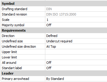
Simbolo
- Norme di disegno
- Visualizza la norma di disegno.
- Revisione standard
- Visualizza la revisione standard.
- Scala
- Imposta la scala delle note.
- Simbolo di maggioranza
- Consente di scegliere se visualizzare o meno il simbolo della maggioranza.
Requisiti
Definisce i requisiti del simbolo di spigolo.
- Direzione
- Definisce la posizione del segno Dimensione non definita.
- Definito
- Il segno si troverà in una posizione definita dalla proprietà Direzione dimensione non definita.
- Non definito
- Il cartello si troverà in una posizione indefinita (centrale).
- Dimensione non definita
- Definisce lo spigolo:
- Nessuno
- Non definisce alcun requisito per il tipo di spigolo. Se disponibili, vengono visualizzati i limiti superiore e inferiore.
- Sbavatura o passaggio consentiti
- Definisce il tipo di spigolo come sbavatura o passante.
- Sottosquadro richiesto
- Definisce il tipo di spigolo come sottosquadro.
- Direzione dimensione non definita
- Definisce la posizione del segno di dimensione non definita.
- Limite superiore
- Definisce il valore superiore digitandolo nella casella o selezionandolo dall'elenco a discesa.
- Limite inferiore
- Definisce il valore inferiore digitandolo nella casella o selezionandolo dall'elenco a discesa.
- Su tutto il profilo
- Aggiunge il contrassegno tutto intorno al simbolo dello spigolo.
- Etichetta standard
- Visualizza la revisione standard accanto al simbolo.
Direttrice
- Punta della freccia principale
- Imposta lo stile della direttrice.