


DIMSTYLE command
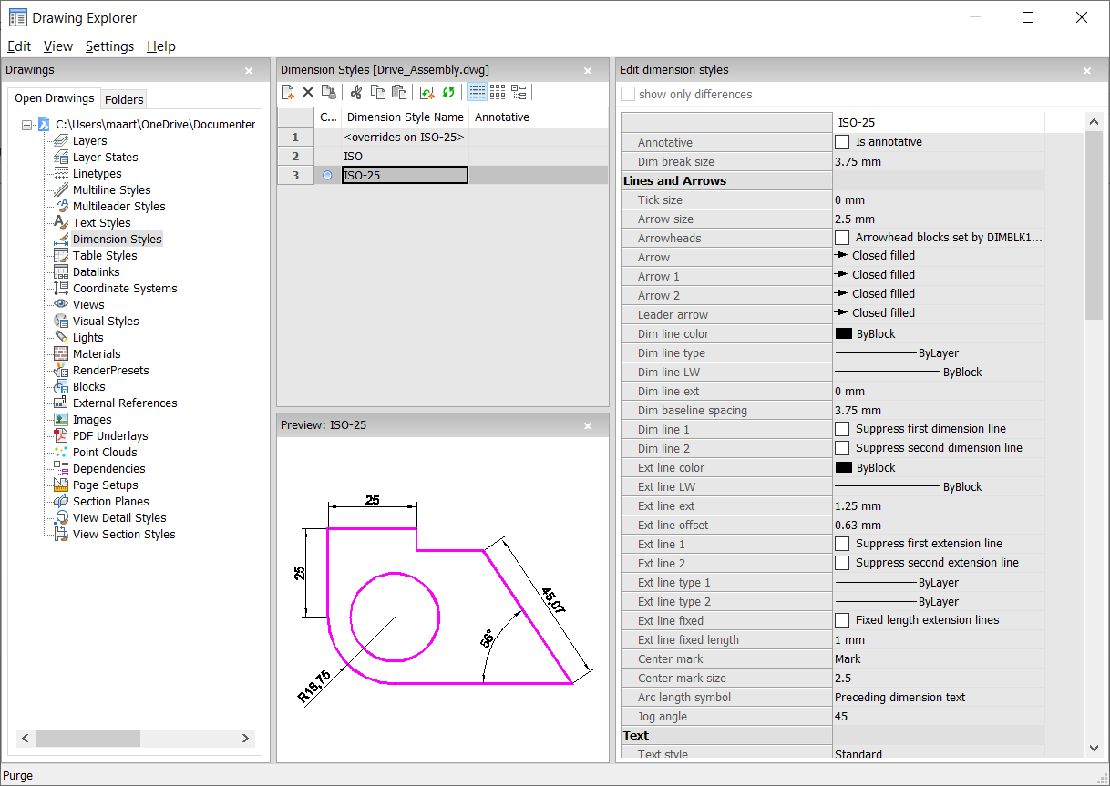
Opens the Drawing Explorer dialog box with Dimension Styles selected.

Icon: 
Alias: D, DDIM, DIMSTY, DS, DST, EXPDIMSTYLES, SETDIM
Description
Opens the Drawing Explorer dialog box with Dimension Styles category selected to view and modify dimension styles in the current drawing.
Method
- <Overrides>: overrides the values of individual dimension variables without creating a new style.
- Standard: lists the dimension settings for the dimension style named "Standard".
Context Menu Options
The following options appear when you right-mouse click on a dimension style:
- New
- Loads additional Dimension Styles definitions into the drawing.
- Delete
- Deletes Dimension Styles definitions from the drawing. The following dimension styles cannot be deleted:
- <overrides on ISO-25>/<overrides on Standard>
- ISO-25/Standard
- Rename
-
Renames the Dimension Styles. The following dimension styles cannot be renamed:
- <overrides on ISO-25>
- ISO-25
- Select All
- Selects all Dimension Styles definitions.
- Invert selection
- Deselects the current selection and vice versa.
- Set current
- Sets the selected Dimension Style as current.
- Save overrides to current style
- Saves the override variables of the selected dimension style to the current dimension style.
- Save to new style
- Creates a new dimension style based on the selected dimension style.
- New child style
-
Creates a new dimension child style. A dimension style can have up to 6 child styles: Linear, Angular, Radius, Diameter, Ordinate, and Leader. If defined, then the child style is used for the corresponding dimension type.
Dimension child styles share all settings with the parent style, except for the properties that are defined explicitly differently.
Options within the command
- Edit dimension styles
- Show only differences
- If multiple styles are selected, compares the selected styles, and shows the differences only.
- Name
-
Names the dimension style. The following dimension styles cannot be renamed:
- <overrides on ISO-25>
- ISO-25
- Annotative
- Sets the annotative property of the dimension style.
- Dim break size
- Sets the value of the gap created by the DIMBREAK command.
- Lines and Arrows
-
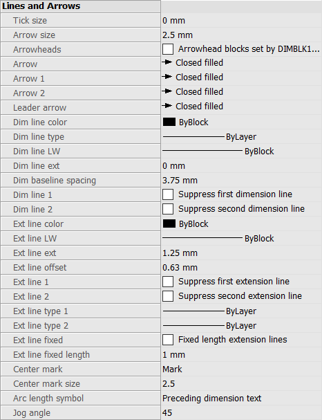
- Tick size
- Determines the size of tick marks drawn instead of arrowheads for linear, radius and diameter dimensioning. If the value is zero, arrowheads are drawn.
- Arrow size
- Determines the size of arrowheads of dimension lines and leader lines.
- Arrowheads
- Controls whether dimension line arrowhead blocks are set by DIMBLK or DIMBLK1 or DIMBLK2.
- Arrow
- Determines the name of the block displayed at the ends of dimension lines and leader lines. The block name can be either a standard name or refer to a user-defined arrowhead block.
- Arrow 1
- Specifies the style of arrowhead for the starting end of the dimension line.
- Arrow 2
- Specifies the style of arrowhead for the other end of the dimension line.
- Leader arrow
- Specifies the style of arrowhead for the starting end of the leader line.
- Dim line color
-
Specifies the color of the dimension line; choose from:
- Any Index Color
- Any True Color
- ByBlock
- ByLayer
- Dim line type
- Specifies the line type of the dimension line. Choose from any line type loaded into the current drawing. To access additional linetypes, click Load..., and then choose one from the Load Linetypes dialog box. See the LINETYPE command.
- Dim line LW
- Specifies the lineweight of the dimension line. Choose from any lineweight supported by the program.
- Dim line ext
- Specifies the distance that the dimension line extends beyond the extension lines.
- Dim baseline spacing
- Specifies the default distance between dimensions added with the DIMBASELINE command.
- Dim line 1
- Toggles the display of the first half of the dimension line (between the starting extension line and the text).
- Dim line 2
- Toggles the display of the second half of the dimension line (between the other extension line and the text).
- Ext line color
-
Specifies the color of the dimension line. To select additional colors, click Select color... and choose one from the Select Color dialog box.
See the COLOR command.
- Ext line LW
- Specifies the lineweight of the extension line. Choose from any lineweight supported by the program.
- Ext line ext
- Specifies the distance that the extension lines extend beyond the dimension line.
- Ext line offset
- Specifies the offset distance between the object and the start of the extension lines.
- Ext line 1
- Toggles the display of the first extension line.
- Ext line type 1
-
Specifies the line type of the first extension line. You can choose from any line type loaded into the current drawing.
To access additional linetypes, click Load... . The Load Linetypes dialog box is displayed where you can choose a linetype.
- Ext line type 2
-
Specifies the line type of the second extension line. You can choose from any line type loaded into the current drawing.
To access additional linetypes, click Load... . The Load Linetypes dialog box is displayed where you can choose a linetype.
- Ext line 2
- Toggles the display of the second extension line.
- Ext line fixed
- Determines whether fixed length extension lines are used.
- Ext line fixed length
- Specifies the total length of the extension lines.
- Center mark
-
Specifies the type of center mark:
- Mark
- Line
- None
- Center mark size
- Specifies the size of the center mark.
- Arc length symbol
-
Specifies the location of the arc length symbol:
- Preceding dimension text.
- Above dimension text.
- Not displayed.
- Jog angle
- Specifies the angle of the jog (default is 45 degrees). Enter another angle.
- Text
-
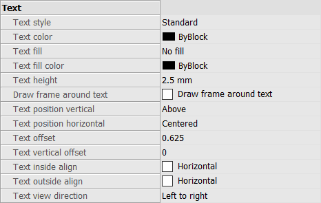
- Text style
- Specifies the style for dimension text; can use only styles created with the STYLE command.
- Text color
- Specifies the color of the text. Click Select color... to select additional color from the Select Color dialog box.
- Text fill
-
Determines whether the dimension text has a rectangular background filled with color.
- No fill: does not apply a background fill.
- Background: uses the background color of the drawing, usually white or black.
- Color: uses the color specified by the Text Fill Color option.
- Text fill color
- Specifies the background fill color when Text Fill is set to Color. You can choose a color from the drop-down list or choose Select Color..., and choose a color from the Select Color dialog box.
- Text height
- Specifies the height of the text.
- Draw frame around text
- Draws a rectangle around the text.
- Text position vertical
-
Justifies the text vertically relative to the dimension line:
- Centered: centers the text on the dimension line.
- Above: places the text above the dimension line.
- Outside: places text outside of the extension lines.
- JIS: places text above the dimension line, according to the Japanese Industry Standard.
- Below: places the text below the dimension line.
- Text position horizontal
-
Justifies the text horizontally relative to the extension lines:
- Centered: centers the text between the extension lines.
- First Extension Line: places the text near the first extension line.
- Second Extension Line: places the text near the second extension line.
- Over First Extension: places the text over the first extension line.
- Over Second Extension: places the text over the second extension line.
- Text offset
- Specifies the size of gap between the dimension line and the text.
- Text vertical offset
- Sets the vertical position of dimension text above or below the dimension line.
- Text inside align
-
Justifies text when located between extension lines:
- Aligned with Dimension Line: aligns text with dimension line.
- Horizontal: forces text to be always horizontal.
- Text outside align
-
Justifies text when located outside of the extension lines:
- Aligned with Dimension Line: aligns text with dimension line.
- Horizontal: forces text to be always horizontal.
- Text view direction
- Sets the dimension text reading direction.
- Fit
-
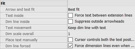
- Arrow and text fit
-
Specifies where text and arrows should be located when there is insufficient space for both between the extension lines:
- Text and Arrows: forces both text and arrows between the extension lines.
- Arrows Only: forces arrows to stay within extension lines; moves text outside when there is insufficient space.
- Text Only: forces text to stay within extension lines; moves arrows outside when there is insufficient space.
- Best Fit: requires the program to figure out where to place text and arrows, depending on the space between extension lines.
- Text inside
-
Specifies whether the text is forced between extension lines:
- On: forces text between extension lines.
- Off: draws text outside if there is insufficient space between extension lines.
- Dim line inside
-
Specifies whether the dimension line is forced between extension lines:
- On: forces dimension line always between extension lines.
- Off: draws dimension line outside if there is insufficient space between extension.
- Text movement
-
Specifies what happens when text is moved away from its default location:
- Keep dim line with text: moves the dimension line with the text, stretching the extension lines.
- Move text, add leader: draws a leader between the text and the dimension line.
- Move text, no leader: does not draw a leader.
- Dim scale overall
-
Specifies the overall scale factor for dimensions. This affects the size of arrows and text only.
This setting is not editable for annotative dimension styles. It is recommended to set Dim Scale Overall = 1 for annotative dimension styles.
- Place text manually
- Toggles whether the user must always specify the text location when creating dimensions.
- Dim line forced
- Forces the dimension line to be always drawn; forces leaders to be drawn with the DIMDIAMETER and DIMRADIUS commands.
- Primary units
-
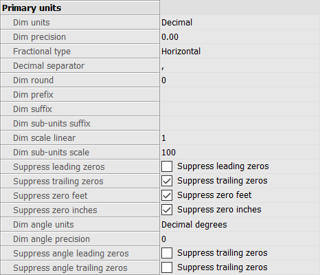
- Dim units
-
Specifies the display units for dimensions:
- Scientific: scientific notation, such as 1.2345E+01
- Decimal: metric, such as 1.2345
- Engineering: feet and decimal inches, such as 1'-2.3456"
- Architectural: feet and fractional inches, such as 1'-2 1/16"
- Fractional: fractional inches only; no feet, such as 14 1/16"
- Windows Desktop: uses the units set by Windows
- Dim precision
- Specifies the precision of units, either decimal places or fractional accuracy.
- Fractional type
-
Specifies how fractions are stacked:
- Horizontal: stacks fractions vertically, with a horizontal separator line.
- Diagonal: stacks diagonally, with a diagonal separator line.
- None: does not stack fractions, placed horizontally with a slash separator.
- Decimal separator
-
Specifies the character used to indicate the decimal point; can be any character.
North American countries use the period; European countries use the comma.
- Dim round
- Specifies the rounding of decimal numbers. The range goes from none to 8 decimal places.
- Dim prefix
- Specifies a prefix text that appears in front of the dimension text, if any.
- Dim suffix
- Specifies a suffix text that appears after the dimension text, if any.
- Dim sub-units suffix
-
Specifies suffix text in case the subunit is used. For example, enter 'cm' to display 0.96 as 96cm.
Note: suppress leading zeros must be set to Yes to display dimension distances less than one unit in sub units.
- Dim scale linear
-
Specifies the scale factor for linear dimension values, such as 25.4 for changing inches to millimeters.
Positive values apply to dimensions in both model space and paper space. Negative values apply to paper space dimensions only.
- Dim sub-units scale
-
Sets the scale factor for the sub-units. For example, enter 10 if the drawing unit is cm, and the subunit suffix is mm.
Note: suppress leading zeros must be set to Yes to display dimension distances less than one unit in subunits.
- Suppress leading zeros
-
Toggles the display of zeros in front of the decimal point. For example, 0.23 is displayed as:
- On: suppresses the leading zero, such as .23
- Off: permits the leading zeros, such as 0.23
- Suppress trailing zeros
-
Toggles the display of zeros after the decimal point. For example, 1.2300 is displayed as:
- On: suppresses trailing zeros, such as 1.23
- Off: allows trailing zeros, such as 1.2300
- Suppress zero feet
-
Toggles the display of zero feet. For example, 0'-3" is displayed as:
- On: suppresses zero feet, such as 3"
- Off: allows zero feet, such as 0'-3"
- Suppress zero inches
-
Toggles the display of zero inches; for example, 1'-0" is displayed as:
- On: suppresses the display of zero inches, such as 1'
- Off: allows zero inches, such as 1'-0"
- Dim angle units
-
Specifies the format of units in angular dimensions:
- Decimal Degrees: 360 degrees in a circle. For example, 123.45 degrees
- Deg/Min/Sec: degrees, minutes, seconds. For example, 123d 12' 45.67"
- Grads: 400 grads in a circle. For example, 230g
- Radians: 2pi radians in a circle. For example, 1.5r
- Dim angle precision
- Specifies the number of decimal places. The range goes from 0 to 8.
- Suppress angle leading zeros
-
Toggles the display of zero degrees. For example, 0.1234 degrees is displayed as:
- On: suppresses zero degrees, such as .1234
- Off: allows zero degrees, such as 0.1234
- Suppress angle trailing zeros
-
Toggles the display of zeros after degrees. For example, 0.1200 degrees is displayed as:
- On: suppresses trailing zeros, such as 0.12
- Off: allows trailing zeros, such as 0.1200
- Alternate units
-
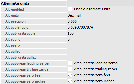
- Alt enabled
-
Toggles the display of alternate units:
- On: second, alternative units displayed to the right of primary units.
- Off: only primary units are displayed.
- Alt units
-
Specifies the alternate unit type for linear dimensions:
- Scientific: scientific notation, such as 1.2345E+01.
- Decimal: metric, such as 1.2345
- Engineering: feet and decimal inches, such as 1'-2.3456"
- Architectural Stacked: such as 4'-6.61''
- Fractional Stacked: such as 54 1/2
- Architectural: feet and fractional inches, such as 1'-2 1/16"
- Fractional: fractional inches only; no feet, such as 14 1/16"
- Windows Desktop: uses the units set by Windows
- Alt precision
- Specifies the precision of alternate units, either decimal places or fractional accuracy.
- Alt scale factor
- Specifies the multiplier for alternate values, such as 25.4 for showing millimeters (alternate units) next to inches (primary units).
- Alt sub-units scale
- Specifies the multiplier for alternate values, such as 25.4 for showing millimeters (alternate units) next to inches (primary units).
- Alt round
- Specifies the rounding of alternate numbers. The range goes from zero to 8 decimal places.
- Alt prefix
- Specifies a prefix text that appears in front of the alternate text, if any.
- Alt suffix
- Specifies a suffix text that appears after the alternate text, if any.
- Alt sub-units suffix
-
Specifies suffix text in case the subunit is used.
Note: suppress leading zeros must be set to Yes to display alternate distances less than one unit in subunits.
- Alt suppress leading zeros
-
Toggles the display of zeros in front of the decimal point. For example, 0.23 is displayed as:
- On: suppresses the leading zero, such as .23
- Off: permits the leading zero, such as 0.23
- Alt suppress trailing zeros
-
Toggles the display of zeros in front of the decimal point. For example, 1.2300 is displayed as:
- On: suppresses trailing zeros, such as 1.23
- Off: allows trailing zeros, such as 1.2300
- Alt suppress zero feet
-
Toggles the display of zero feet; for example, 0'-3" is displayed as:
- On: suppresses zero feet, such as 3" Off: allows zero feet, such as 0'-3"
- Alt suppress zero inches
-
Toggles the display of zero inches. For example, 1'-0" is displayed as:
- On: suppresses the display of zero inches, such as 1'
- Off: allows zero inches, such as 1'-0"
- Tolerances
-
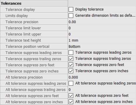
- Tolerance display
- Toggles the display of tolerance text.
- Limits display
- Sets the default text to dimension limits.
- Tolerance precision
- Specifies the display precision of tolerance text. The range goes from 0 to 8 decimal places or 1/1 to 1/256 inch.
- Tolerance limit lower
- Specifies the value of the upper tolerance.
- Tolerance limit upper
- Specifies the value of the lower tolerance.
- Tolerance text height
- Specifies the height of the tolerance text.
- Tolerance position vertical
-
Locates the tolerance text relative to the dimension text:
- Bottom: aligns tolerance text with the bottom of the dimension text.
- Middle: aligns tolerance text with the middle of the dimension text.
- Top: aligns tolerance text with the top of the dimension text.
- Tolerance suppress leading zeros
-
Toggles the display of zeros in front of the decimal point. For example, 0.23 is displayed as:
- On: suppresses the leading zero, such as .23
- Off: permits the leading zero, such as 0.23
- Tolerance suppress trailing zeros
-
Toggles the display of zeros behind the decimal point. For example, 1.2300 is displayed as:
- On: suppresses trailing zeros, such as 1.23
- Off: allows trailing zeros, such as 1.2300
- Tolerance suppress zero feet
-
Toggles the display of zero feet; for example, 0'-3" is displayed as:
- On: suppresses zero feet, such as 3"
- Off: allows zero feet, such as 0'-3"
- Tolerance suppress zero inches
-
Toggles the display of zero inches. For example, 1'-0" is displayed as:
- On: suppresses the display of zero inches, such as 1'
- Off: allows zero inches, such as 1'-0"
- Alt tolerance precision
- Specifies the number of decimal places for tolerances in alternate units.
- Alt tolerance suppress leading zeros
-
Toggles the display of zeros in front of the decimal point. For example, 0.23 is displayed as:
- On: suppresses the leading zero, such as .23
- Off: permits the leading zero, such as 0.23
- Alt tolerance suppress trailing zeros
-
Toggles the display of zeros behind the decimal point. For example, 1.2300 is displayed as:
- On: suppresses trailing zeros, such as 1.23
- Off: allows trailing zeros, such as 1.2300
- Alt tolerance suppress zero feet
-
Toggles the display of zero feet; for example, 0'-3" is displayed as:
- On: suppresses zero feet, such as 3"
- Off: allows zero feet, such as 0'-3"
- Alt tolerance suppress zero inches
-
Toggles the display of zero inches. For example, 1'-0" is displayed as:
- On: suppresses the display of zero inches, such as 1'
- Off: allows zero inches, such as 1'-0"