


VIEWBASE command
Generates associative orthographic and isometric views of 3D models in paper space layouts.

Icon: 
- This command is valid in Model Space only.
- Use the Tab key to select obscured entities.
- When the GENERATEASSOCVIEWS (Generate associative drawings) system variable is ON, associative dimensions for generated views are updated automatically when the 3D model is modified.
- Setting the GENERATEASSOCATTRS (Generate associative attributes) system variables ON, allows VIEWBASE to generate drawings in which dimensions and tags are updated automatically when the 3D model has been modified.
- The DRAWINGVIEWQUALITY system variable defines the quality of drawing views.
- The DRAWINGVIEWFLAGS system variable enables parallel creation or updating of drawing views. This can reduce view processing time, but uses more resources.
- The DRAWINGVIEWASM system variable enables the use of assembly data structures to optimize generation of drawing views.
- This command can be entered transparently during commands (‘viewbase).
Method
Select one or more entities (3D solids, blocks, components) or press Enter to select all 3D entities in the Model Space from which to generate the drawing views in a layout tab or choose an option. Hit the Tab key to select nested entities.
Enter the name of a new or existing layout or press Enter to accept the current layout.
The command switches to the layout tab where a point must be picked to define a position for the base view or enter an option.
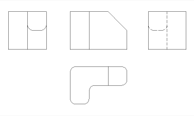
Select the position for each projected view by moving the cursor. Depending on the position of the cursor with respect to the base view one of five orthogonal views (top, left, right, back and bottom) and four isometric views can be inserted. The views are aligned automatically depending on the selected projection type (see above).
Tap the Ctrl key to toggle alignment ON and OFF. When it is off, you can place the current view in any location.
Options within the command
- Entire model
- Selects all the 3D entities in model space.
- preseTs
- Specifies the types of generated drawings and their placement in the layout; displays the Drawing View Presets dialog box.
- Special views
- Selects a style of exploded representations, if any exist in the drawing.
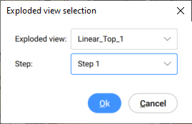
- Exploded view
-
Creates an exploded drawing view if an exploded representations exists in the drawing.
The created views correspond to the selected step when selected. For "<All steps>", the views should correspond to the final state of the exploded view (last step).
- Unfolded view
- Creates an unfolded drawing view for solids with associated unfolded view.
- Back
- Returns to the previous prompt.
- Scale
- Sets the Scale property of the paper space viewports for the various views:
- fit 4 views
- The scale is adjusted to fit the four standard orthographic views: Front, Top, Left, Right. The Front view (base view) is defined by the Orientation option.
- fit 9 views
- Adjusts the scale to fit five orthographic views and four isometric views.
- fit 5 views
- Adjusts the scale to fit five orthographic views: Front, Top, Left, Right, Back.
- fit 10 views
- Adjusts the scale to fit six orthographic views and four isometric views.
- Standard scales
- Displays the scale list as maintained by the SCALELISTEDIT command; select a scale from the list.
- Custom scales
- Prompts you to type a scale in the Command line.
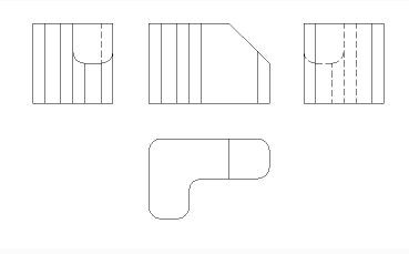
- Hidden Lines
- Controls the visibility of hidden lines.
When the BM_Ortho_Hidden and BM_Isometric_Hidden layers are off or frozen, hidden lines will not display.
- Tangent Lines
- Toggles whether tangent edges between tangent faces are created. Visible tangent edges are created on the BM_Tangent_Visible layer. Hidden tangent edges are created on the BM_Tangent_Hidden layer.
- No
- Does not display tangent lines.
-
- Yes
- Displays the tangent lines.
-
-
- INterferance edges
- Toggles between ON and OFF the visibility of interference edges between solids which intersect with each other. When it is ON, a line is drawn where the solids are met.
- trailiNg lines
- Controls the visibility of trailing lines.
To create exploded views, use the BMEXPLODE command; the model must have inserts of mechanical components to use this command.
- Orientation
- Defines the base view orientation. Rotates the 3D model so that the main view is projected on the vertical projection plane (V.P.).
- Projection type
- Defines the layout of the views.
- First angle
- It is also known as European projection.
- Third angle
- It is also known as American projection.
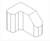
- Isometric Geometry
- Defines the style for the isometric views: rendered 3D view or 2D drawing:
- 2D views
- Draws isometric views as 2D drawings.
- 3D views
- Draws isometric views as 3D solids with the Conceptual visual style applied.
- sElect
- Selects additional entities to include or exclude.
- Remove
- Removes entities from drawing views.
- Entire model
- Includes all entities from model space in the drawing views.
- Layout
- Opens the previous layout with updated drawing views.