


VIEWSECTION command
Creates cross-section views of drawing views generated with the VIEWBASE command in a paper space layout.

Icons: 


Note:
- This command operates only in Paper Space.
- When the GENERATEASSOCVIEWS (Generate associative drawings) system variable is ON, associative dimensions for section views are updated automatically when the 3D model is modified.
- If the SECTIONABLE property of a mechanical component is OFF, the component appears non-sectioned in the section views of the Full section type.
- DRAWINGVIEWQUALITY variable defines the quality of drawing views.
- The AUTOVPFITTING variable controls whether the size of the viewport is adjusted automatically to fit the current extents of the 3D geometry. By default AUTOVPFITTING = ON.
- This command can be entered transparently during commands (‘viewsection)
Method
Select the drawing view to generate the section by clicking inside a drawing view. The program highlights the selected view. Create a section and choose a location for the result view.
Options within the command
- Select type
- Control the shape of the section plane:
- Full
- The section line defines an infinite plane that cuts through the entire model.
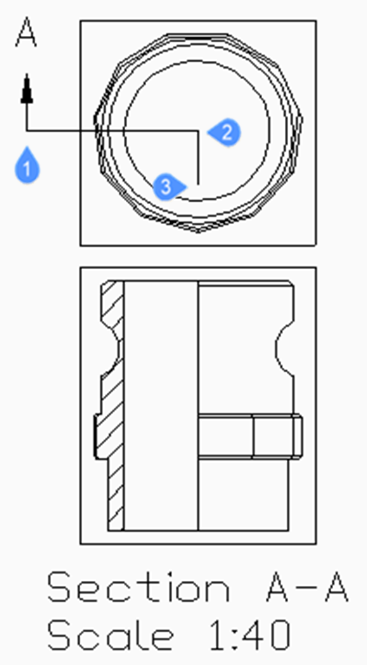
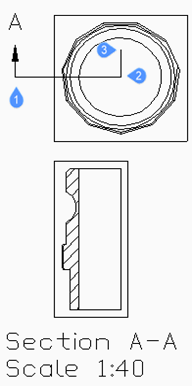
- Half
- The section line defines a half-plane that cuts part of the model. You must specify by clicking the start point (1) of section line, the second point (2) to define the limit of the half plane and the third point (3) to define the view direction.
-
- Offset
- The section line defines a series of cutting regions located on different offsets from each other. Enter Done to complete the section line.
- Aligned
- The section line defines a polyline, where every segment defines a cutting region. The resulting section will have the length equal to the sum of the lengths of cutting regions. Enter Done to complete the section line.
- Scale
- Specifies the scale of the detail view, which by default is twice the parent viewport scale.
- Standard scales
- Choose a standard scale from the list; the list can be edited by the SCALELISTEDIT command.
- Custom
- Specify a custom scale factor.
- from Parent
- Sets the scale of the section view equal to the scale of the parent view.
- Hidden lines
-
Control the visibility of hidden lines or : uses the same hidden lines setting as the parent view.
Note: When the BM_Ortho_Hidden and BM_Isometric_Hidden layers are off or frozen, hidden lines will not display.
- Tangent lines
- Controls the display of tangent edges which appear in the transition from a flat face and a curved face, such as with fillets.
- anChor
- Determines if the center of the viewport is anchored so that the viewport grows and shrinks around its center point or if the geometry is fixed.
- Geometry
- Selects the visual style for the section view.
- 2D
- The section view uses the 2dWireframe visual style.
- 3D
- The section view uses a rendered visual style. This is Conceptual by default. Use the Properties panel to choose a different visual style.
- Annotation
- Determines the annotations to use.
- Identifier
- Specifies the view detail identifier by entering a name for the view detail.
- Label
- Toggles the display of the view detail label.
- Depth
- Specifies the view depth of a section view.
- Full
- Sets the depth to the extents of the model (maximum view depth).
- Custom
- Limits the view depth by entering the depth distance (type a positive value or move the cursor to define the view depth dynamically).
- Projection
- Determines how the section is projected.
- Normal
- Draws the section as a union of projections from every cutting region (each segment of the section polyline) in its normal direction.
- Orthogonal
- Draws the section in the normal direction of the first section region (the first segment of the section polyline).
- Rotate view
- Allows you to rotate the drawing view viewport but does not rotate the frame.
- Horizontal
- Rotates a segment horizontally.
- Vertical
- Rotates a segment vertically.
- Custom angle
- Allows you to specify the angle of alignment.
Grips Editing
You can edit section lines with grips.
Selecting either the section line, one of the identifiers or an arrow, 5 Grips display:
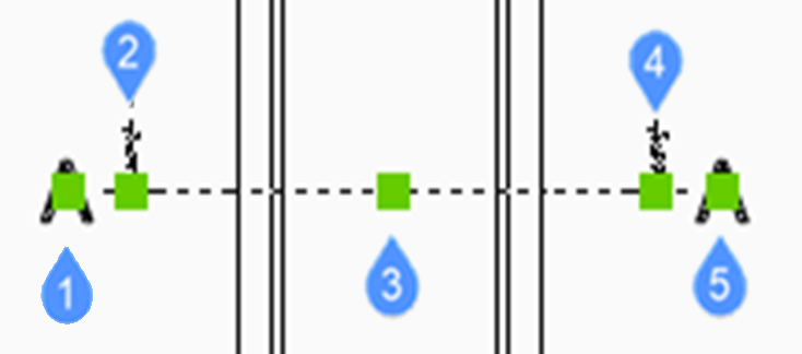
- Controls the position of the first identifier.
- Defines the start point of the section line.
- Allows you to move the section line.
- Defines the endpoint of the section line.
- Controls the position of the second identifier.