


2D parametric blocks
Context
Parametric blocks are blocks which contain not only pure geometry, but also some metadata, which affect the geometry (for example their size, visibility). The metadata controls the way the block references behave. Thus, the size and appearance of a parametric block can be modified without editing the block definition.
Workflow
This workflow will describe one way of working with 2D Parametric Blocks, making use of some advanced features that BricsCAD® offers for creating these blocks.
One use case of the 2D Parametric Blocks is architectural symbols. The symbol used in this example is a simple parametrized door.
Creating the geometry
To ensure all the necessary tools are easily accessible, it is helpful to set the workspace to Drafting.
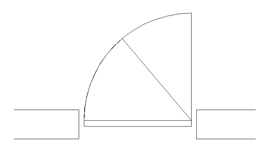
The geometry will contain the entities to represent three distinct configurations of the door. These configurations are called visibility states. When creating the geometry, the entities for all the states will be drawn.
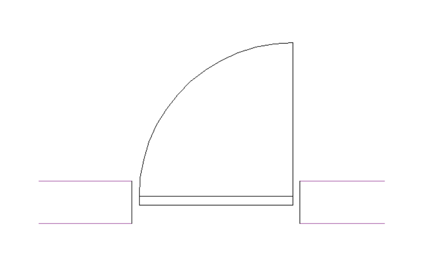
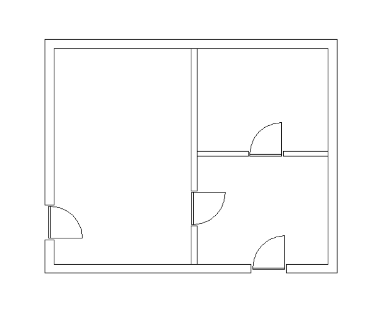
For this example, the block geometry will look like this:
Adding the visibility states
To start creating the visibility states, open the Visibility States panel. To do this, go to the 2D Parametric tab of the ribbon. In the Operations panel, click the Visibility button (or right-click the ribbon and select ). You can also launch the VISIBILITYSTATESPANELOPEN command in the Command line.
For more information about the visibility states, see the article Visibility states panel.
Next, three states of the door symbol will be defined. These states are created as values of a visibility parameter. This operation can be achieved using the Visibility States panel mentioned above.
The workflow for this task is the following:
- Create a visibility parameter.
- Add three states to it.
- Add entities to the parameter.
- Make attached entities visible or invisible depending on which state is active.
To add the visibility states to the block, follow the next steps:
- Open the block drawing.
- To add a visibility parameter, click the Add parameter button (
 ) at the top of the Visibility States
panel. A new parameter will be created, and its name will be available to edit. For this example,
the visibility parameter will be called Angle.
) at the top of the Visibility States
panel. A new parameter will be created, and its name will be available to edit. For this example,
the visibility parameter will be called Angle. - To add a state, click the +Add state button under the parameter name label. A new visibility state is created, and its name is available for edit. For this example, the names of the three visibility states are Open, Half Open and Closed.
- To add entities to a state, hover over the state name label and click the menu button (
 ) that appears at the right end. From the context menu, choose Make entities visible. This option allows you to select the entities that will be made visible to this state only. To attach entities to each of the three states, follow the next steps:
- Make the Open state active and add the vertical line and the larger arc.
- Make the Half Open state active. The entities added to Open will be hidden. Add the slanted line and the smaller arc.
- Make the Closed state active. The entities for Open and Half Open will be hidden. Because the entities for the other states have been automatically hidden when they were attached, there are no changes to be made. This happens for the last state of the parameter.
Note:- When a certain visibility state is active, to view the entities that are hidden for that state, click the menu button () at the top right corner of the panel and then click Show invisible. The hidden entities will be shown in light blue. To hide them again, deselect the Show invisible option.
- There is a second way to add entities to a visibility parameter. Click the arrow button (>) at the right of one of the state name. A new state specific panel opens. Then click the Select add (
 ) button at the top of the panel and select the desired entities.
 - To remove entities from a visibility parameter, click the arrow button (>), then click the Select remove (
 ) button and select the entities to be removed from the parameter.
 - If, by mistake, some entities are specified to be visible in all the states of the parameter, they will appear in the state specific panel with the label Visible for all states of this parameter. These entities are redundant, and they should be removed from the parameter.
- To remove many entities at once, select them using the Shift key. Then, right-click and select Remove from parameter.
- To edit the visibility of the entities for a certain state, make the state active and click the arrow button (>). The state specific panel opens and displays a list containing the entities that are attached to the parameter. At the left side of each entity label there is an eye icon. If the eye icon has a slanted line over it (
 ), then the entity is hidden for that state. Clicking on the icon will toggle the visibility of that entity.
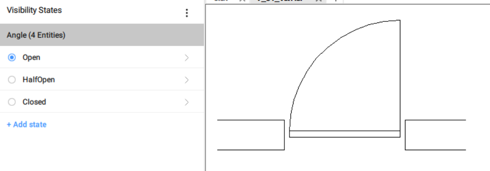
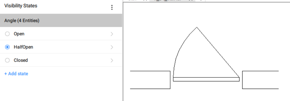
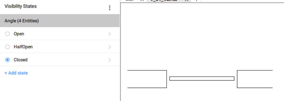
This is how the block will look for each visibility states that were defined:
- Save the block drawing.
- Insert the block into the target drawing.
- To change the visibility state, follow these steps:
- Select the block.
- Open the Properties panel and go down to Parameters section.
- Select a visibility state from the Angle parameter drop-down list.
Adding the reference curves
Reference curves are entities which are created on the REFERENCE_CURVES layer. These specific entities of a block will be used to align it with entities in the target drawing. The alignment will take place during the insert operation.
The block will be placed in the desired position without the need of further editing operations as moving or rotating.
For more information on reference curves, see the article REFERENCECURVES command.
To add the reference lines, follow the next steps:
- Open the block drawing.
- Launch the REFERENCECURVES command in the Command line. You can also go to the 2D Parametric tab of the ribbon. In the Operations panel, click the Reference curves button.
- Select the four horizontal lines that represent the wall. These lines are now put on the REFERENCE_CURVES layer.
- Save the block drawing. The block will look like this:
 Note: At this stage, the block will snap the reference curves to similar curves in the target drawing. For this case, the block contains two times two parallel lines, with an offset distance of 300 mm. Thus, this block will be dynamically snapped to lines in the target drawing that are parallel with an offset distance of 300 mm.
 -
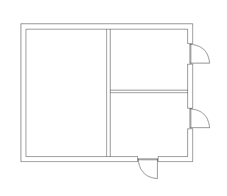
Insert the block into the target drawing. After a few insertions, the result will be similar to this:
The insertion process is like this:
After launching the INSERT command, the Insert Block dialog opens. In the Advanced settings section, make sure the checkbox Use reference curves for insert is ticked, then press OK. The block will be loaded and attached to the mouse cursor. When moving in the neighborhood of two lines that match the reference curves in the block, the block will snap to those lines. Here is a capture of this snapping behavior:
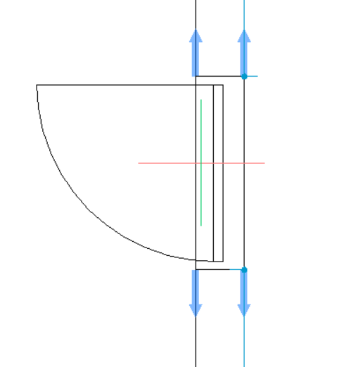
The four blue arrows represent the reference curves in the block. The block will be aligned to matching lines. Moving the mouse along the lines allows you to position the block. Left clicking the mouse will insert the block in the drawing, aligned to the matching lines. In this specific use case, the lines in the target drawing will be trimmed between the connection points (i.e., the points at which the reference curves arrows are attached).
If the lines under the mouse cursor do not match the reference curves, the block can be inserted in the normal way, but will not align with any curves in the target drawing. For this case, if the distance between the parallel lines in the drawing is different than 300 mm (as it is in the block), the reference curves will not snap to those lines.
Note: The reference curves might not work well with the geometric and dimensional constraints. The behavior of the block when applying reference curves together with constraints is highly dependent on the complexity of the block geometry and the number and type of the constraints.Note: The Fuzzy Insert Guided functionality parametrizes reference curves to enable you to insert the door block in walls (pairs of parallel lines) with different wall thicknesses (distances between the lines).
Enabling the Fuzzy InsertGuided functionality
To make the door block more flexible/fuzzy, the reference curves will be parametrized, and the surrounding geometry will be constrained to them. As a result, the parametric block will snap to walls with different wall thicknesses in the target drawing.
For more information on this functionality see the article Fuzzy Insert Guided Workflow.
To enable the Fuzzy InsertGuided functionality to the block, follow the next steps:
- Open the block drawing.
- Launch the REFERENCECURVES command from the ribbon or the Command line. For this case, the reference lines are already defined.
- Select the Parametrize option. This will create the parameters between the reference curves automatically (see the panels Parameters Manager or Mechanical Browser).
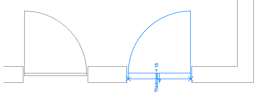
- Add constraints to attach some entities to the parametrized reference curves. See the picture
below:
For this case, four coincident constraints were added between the ends of the reference curves and the ends of the two vertical lines that represent the wall break.
- Save the block drawing.
- Insert the block into the target drawing. This time, due to the parameters attached to them, the
reference curves will also snap to the inner walls which have a different thickness. See the picture
below.
Adding the flip lines
Another useful feature that can be added to the parametric blocks is flipping the block geometry along certain lines. This task can be achieved using a flip parameter. The flip parameter will mirror the block across one axis. For this example, two flips will be added, mirroring horizontally and vertically.
To have access to the flip functionality, go to the 2D Parametric tab of the ribbon. In the Operations panel, click the button Flipline. Another way to achieve a flip operation is by typing the FLIPLINE command in the Command line.
For more information on the flip lines, see the article FLIPLINE command.
To add one flip line, follow the next steps:
- Open the block drawing.
- Launch the FLIPLINE command in the Command line and draw a vertical line on the center of the block. This command creates an orange line.
- Individually select entities to be flipped or use the flip Everything option.
- Give a name to the flip parameter. This parameter will be named flip_Horizontally.
- Using the same process, define a new flip line on the middle of the wall. This will be called
flip_Vertically.
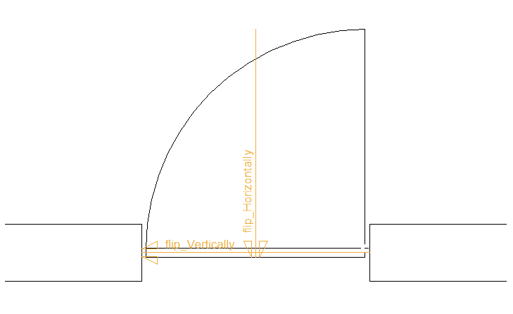
After defining the flip lines, the block drawing will look like this:
- Save the block drawing.
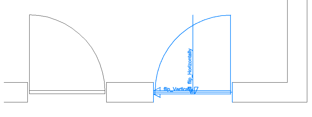
- Insert the block into the target drawing. After that, the block can be flipped by selecting it
and using the flip parameters in the Parameters section of the
Properties panel.
- (Optional) Change the parametric block operation geometries color by setting the POPERATIONSCOLOR system variable as needed.
- The parametric block operation geometries are visible by default after these are created, but hidden when opening a drawing that contains parametric blocks. Use the PBLOCKOPERATIONSDISPLAY command to hide/show the parametric block operation geometries.
- The visualization of the parametric operation geometries when hovering the cursor over parametric block references is controlled by the PBLOCKREFERENCEOPERATIONSVISUALIZATION system variable (Off by default).
Adding the stretch parameter
The stretch parameter works similar to the STRETCH command. It can be useful when there are many entities to be stretched or moved in the same direction, over the same distance, without editing the block. In this case, the stretch parameter can replace several constraints, thus simplifying the drawing and the process of parametrizing the geometry.
For more information on the stretch parameter, see the article PARAMETRICSTRETCH command.
The following steps describe how to add a parametric stretch to a block:
- Open the block drawing.
- Launch the PARAMETRICSTRETCH command in the Command line. You can also go to the 2D Parametric tab of the ribbon. In the Operations panel, click the Stretch button.
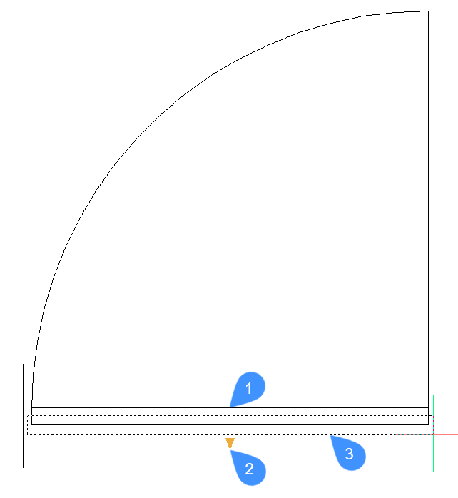
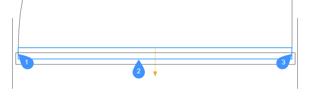
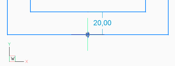
- Create the stretch vector by selecting two points. For this example, the stretch vector will
have its base point of displacement in the point marked with 1, and the second point of
displacement, in the point marked with 2. See the picture below.
 Note:
Note:- The direction of this vector defines the direction of the stretch, and the length of this vector will be the initial value of the stretch parameter.
- If possible, align the vector with an important feature/dimension in the drawing. By doing this, the stretch parameter value will have a clear meaning.
- The stretch vector is drawn with a soft red color so it should be easily observed.
-
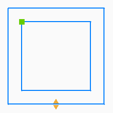
Draw the stretch frame.
The stretch frame can be a polygon or a rectangle. The stretch frame is used to specify which stretch points will be moved when the stretch is applied. Only the points of selected entities (see next step) which lie inside the stretch frame will be moved.
For this example, the stretch frame will be the rectangle marked with 3 in the picture above.
-
Edit the selection of the entities which will be affected when a stretch is applied, if needed. By default, the entities that have stretch points inside the stretch frame are already selected.
For this example, the default selection includes the lower line and the two side lines of the rectangle. See the highlighted lines marked with 1, 2 and 3 in the picture below.
- (Optional) Change the linked behavior of the stretch operation to have entities follow operation definition points when adjusted by other operations. The Off option corresponding to not linked behavior is set as default for newly created parametric operations.
- Give a name to the stretch parameter. For this example, the parameter will be named Thickness.
- Save the block drawing.
- Insert the block in the target drawing and change the stretch parameter.
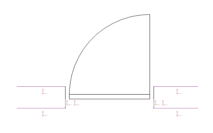
The block on the left has its Thickness parameter set to the default value of 60 mm. The block on the right has its Thickness parameter changed to 150 mm. This might make sense for insulation purposes, in this use case.
- The parametric block operation geometries are visible by default after these are created. You
can use the PBLOCKOPERATIONSDISPLAY command to hide them. Use the same command to show them back.Note: Points of parametric operations that are affected by a parametric stretch operation are marked by an "X".
Grip editing a parametric block
- Flip
- Stretch
- Move
- Scale
- Rotate
- Offset
- Select a parametric block in the drawing.
The grip points corresponding to the block reference's parametric operations are displayed.
- Hover the cursor over a parametric operation grip point.
The current value of the parametric operation is displayed.
- Click the operation grip point.
The dynamic input field is activated.
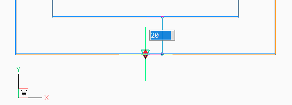 Note: For parametric flip operations, click the grip point to mirror the block.
 - Drag the selected operation grip point.
The parametric operation's value is updated dynamically.
- Click again to set the new value of the parameter or type a value in the dynamic input field.
The block reference's appearance is updated according to the new parametric operation's value.