2D constraints
2D parametric constraints are used to maintain relationships and control dimensions of 2D geometry.
- Geometric constraints control relationships between entities.
- Dimensional constraints are used to control the dimensions of an entity, such as length, angle, radius or diameter.
- It is recommended to first apply geometric constraints, then dimensional constraints.
- The PARAMETERCOPYMODE system variable controls how constraints and related parameters are processed when constrained entities are copied.
- The PARAMETRIZE2D command automatically creates geometric and dimensional parameters.
A dimensional constraint can use a value or a formula, with other dimension constraints or parameters. Dimensional constraints can be edited in the Properties panel, the Parameters Manager panel, and the Mechanical Browser panel.
- The Properties panel by changing for the selected dimensional constraints the value of the Reference property from No to Yes.
- The Mechanical Browser panel by changing the value of the Geometry-driven field from Off to On.
The reference parameters are displayed within brackets in model space, paper space, and in the Mechanical Browser panel. All reference parameters in the drawing are listed in the Parameters Manager under the Reference Parameters category.
- Underconstrained: some entities are constrained. It might be impossible to apply some changes using modification commands and procedures.Note: For underconstrained entities created with BricsCAD V23, you must set the 2DCONSTRAINTFLAGS system variable value to 1.
- Fully constrained: all possible and relevant geometric and dimensional constraints are applied to the design geometry. The drawing can be modified only by changing the values of the dimensional constraints.
- Overconstrained: one or more constraints violate or contradicts other constraints.
- Maintain geometric design intent.
- Make multiple versions of a design by applying different values to dimensional constrains.
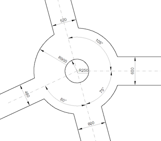
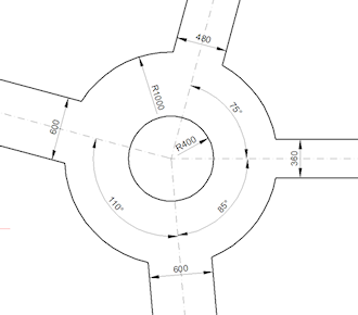
Two versions of the same fully constrained drawing representing a roundabout:
Commands and toolbars
2D parametric constraints tools are located on the 2D Constraints toolbar and the 2D Parametric ribbon tab.
Tools to control the display of constraint bars and geometric constraints are located on two flyout toolbars, Dimensional Constraint and Geometric Constraint.
The CONSTRAINTBAR command controls the display of the constraint bar of entities. Constraint bars are always hidden when opening a drawing.
The DELCONSTRAINT command removes all dimensional and geometric constraints from an entity.
- Dimensional constraints commands
-
Command Description DCDISPLAY command Allows to set dimensional constraints to be displayed or hidden. DIMCONSTRAINT command Applies a dimensional constraint to an entity or between constraint points on entities.
Converts associative dimensions to dynamic dimensions.
DCHORIZONTAL command Constrains the horizontal distance (X-distance) between two points with respect to the current coordinate system. DCVERTICAL command Constrains the vertical distance (Y-distance) between two points with respect to the current coordinate system. DCLINEAR command Constrains the horizontal distance (X-distance) or vertical distance (Y-distance) between two points with respect to the current coordinate system. DCALIGNED command Constrains the distance between two points or the length of a line or polyline segment. DCRADIUS command Constrains the radius of a circle, an arc or an arc polyline segment. DCDIAMETER command Constrains the diameter of a circle, an arc or an arc polyline segment. DCANGULAR command Constrains the angle between two lines or linear polyline segments; the total angle of an arc or an arc polyline segment; or the angle between three points on entities. DCCONVERT command Converts an associative dimension to a dimensional constraint.
- Geometric constraints commands
-
Command Description GEOMCONSTRAINT command Applies geometric relationships between entities and/or valid constraint points on entities. GCFIX command Constrains points and entities at a fixed position. GCCOINCIDENT command Applies a coincident geometric constraint to two points or constraints a point to an entity.
GCCONCENTRIC command Constrains the center points of circles, arcs, ellipses or elliptical arcs to coincide. GCCOLLINEAR command Forces lines or polyline segments to be collinear. GCPARALLEL command Forces two lines or linear polyline segments to be parallel to each other. GCPERPENDICULAR command Constrains two lines or polyline segments to lie perpendicularly to each other. GCTANGENT command Constrains two entities to maintain a point of tangency to each other or their extensions.
The following entities are accepted: lines, polyline segments, circles, arcs, ellipses or elliptical arcs.
GCHORIZONTAL command Constrains lines, linear polyline segments or pairs of points to lie parallel to the X-axis of the current coordinate system. GCVERTICAL command Constrains lines, linear polyline segments or pairs of points to lie parallel to the Y-axis of the current coordinate system. GCSMOOTH command Forces a spline to maintain fluid geometric continuity with another spline, line, arc or polyline. GCSYMMETRIC command Constrains two entities or points to lie symmetrically with respect to a selected line. GCEQUAL command Constrains arcs and circles to the same radius, or lines and polyline segments to the same length.