


The manipulator
The manipulator is a versatile grip tool to swiftly move, rotate, scale and mirror selected entities. Holding down the Ctrl key when starting the action keeps the original entities, creating copies. When selecting an entity, the manipulator is displayed at a user-controlled location and orientation. The location and orientation are controlled in a similar way to a dynamic UCS. When multiple entities are selected simultaneously, the manipulator is displayed at their geometric center. When a selection is built up step by step, the initial location of the manipulator is preserved. The manipulator can be moved to any desired location or orientation using its handles and the context menu options.
Depending on the operation type and if dynamic dimensions are active, a dynamic entry field is available to set the distance, angle or scale factor.
Adaptive snap step
The snap step size automatically adapts to the current screen zoom factor if SNAPTYPE= 2. The ADAPTIVEGRIDSTEPSIZE system variable controls the smallest available step size. The adaptive step size is used to dynamically adjust the step size in the Manipulator Ruler, which enables you to quickly modify entities using precise values, without having to key in numbers.
The manipulator settings
The manipulator settings can be found in the Settings dialog box under .
When the Manipulator is displayed, select Manipulator Settings in the right-click context menu.
The manipulator layout
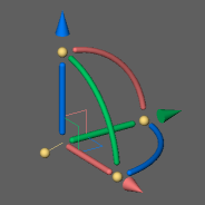
Check the Classic Color option in the manipulator context menu for the classic layout. Untick the option for the default layout.
|
|
| Default | Classic |
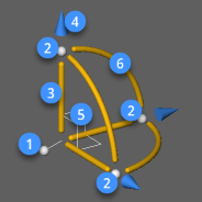
4 handles
- 1: manipulator handle
- 2: axis handle
12 command trigger zones
- 3: axis
- 4: arrowhead
- 5: plane swatch
- 6: rotation arc
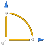
When the current view is parallel to one of the main axes of the coordinate system, as in a plan view, the manipulator is simplified to a 2D version.
The location and orientation of the manipulator
The initial location and orientation of the 3D manipulator tripod depends on:
- The entity type.
- The point you click on the entity.
| Entity Type | Selection Point | Manipulator - Anchor Point | Manipulator - Orientation |
|---|---|---|---|
| Line | Near endpoint | At endpoint | X-axis through the other endpoint |
| Line | Near midpoint | At midpoint | X-axis through the nearest endpoint |
| Polyline Line Segment | Near vertex | At vertex | X-axis through the other vertex of the selected line segment |
| Polyline Line Segment | Near segment midpoint | At the segment midpoint | X-axis through the nearest vertex |
| Polyline Arc Segment | On the arc segment | At the arc center | X-axis through the nearest vertex |
| Arc | Random | At the arc center | X-axis through the nearest endpoint |
| Circle | Random | At the circle center | X-axis parallel with the X axis of the current coordinate system |
| Spline | Random | At the nearest endpoint | Through the other endpoint |
| Region | On a line segment | At the nearest endpoint of the line segment | X-axis through the other endpoint |
| Region | On an arc segment | At the center of the arc segment | X-axis through the nearest endpoint of the arc segment |
| Text, MText, Block, Xref | Random | At the origin of the entity | X-axis at the rotation angle of the entity |
| 3D Solid 3D Solid Face |
On a face of the solid | At the nearest vertex | X-axis along the nearest edge XY-plane in the selected face |
| Multiple Entities | Random | At the geometric center of the selection set** | Parallel with the axes of the current coordinate system |
* See Selection Modes to learn how to select a 3D solid face or the entire solid.
** The position of the manipulator does not change when more entities are added to the selection set.
Displaying the manipulator
The value of the MANIPULATOR system variable controls when the MANIPULATOR appears automatically upon selection:
- 0: Do not display Manipulator
- 1: Display Manipulator when entities are selected
- 2: Display Manipulator if the left mouse button is pressed longer than the duration defined in the MANIPULATORDURATION system variable.
In order to display the Manipulator when multiple entities are selected:
- Select the entities one by one or use window selection, then long-click to select the last entity.
- Set the value of the MANIPULATOR system variable to 1.
- Compose the selection set, then launch the MANIPULATE command.
Moving the manipulator
Do one of the following:
-
Long-click anywhere on the manipulator and move it to a new location.
- MANIPULATORHANDLE = 0: Click the manipulator handle (1) and move it to a new location*.
The anchor handle stands out to avoid overlap with entity grips.
-
MANIPULATORHANDLE = 1: Long-click the manipulator handle (1) and move it to a new location*.
- Place the cursor over the manipulator, then right-click and choose Move in the context menu and move it to a new location*.
* Specify the new location using entity snaps.
Rotating the manipulator
Select one of its axis handles (2) to rotate the manipulator. Pick a point or type a value in the dynamic entry field to specify the rotation angle.
Press the Shift key to rotate the Manipulator 90 degrees around its normal axis (Z-axis).
Reorienting the manipulator
- Place the cursor over the manipulator, then right-click and choose Reorient Manipulator in the context menu.
You are prompted: Specify origin of manipulator:
- Pick a point.
The anchor point of the manipulator is placed at the specified point.
You are prompted: Point on X-axis or <Accept>:
- Pick a point.
The manipulator rotates about its X-axis.
You are prompted: Point on the XY-plane with positive Y value or <Accept>:
- Pick a point to define new position of the manipulator.
Aligning the manipulator with a coordinate system
Move the cursor over the manipulator, then right-click and select an option in the context menu:
- Align with WCS: the manipulator axes are forced to become parallel to the corresponding axes of the World Coordinate System.
- Align with UCS: if a UCS is currently the active coordinate system, the manipulator axes are forced to become parallel to the corresponding axes of the UCS.
Aligning the manipulator with the face of a solid
Dynamic UCS (DUCS) must be ON for this operation to succeed.
- Place the cursor over the manipulator then right-click and choose Move in the context menu.
- Hover over the face of a solid.
The XY-plane of the manipulator aligns with the solid face under the cursor.
- Do one of the following:
- Snap to a point on the selected face or on one of its edges.
- Press the Shift key to lock the XY-plane to the selected face, then snap to a point outside the face.