


Parametric modeling overview
BricsCAD® provides a rich toolset to control 2D and 3D geometric models with parameters of different kinds. This includes:
- Global parameters: parameters of 2D/3D dimensional constraints, user-defined parameters, configuration parameters of design tables, etc.
- Local parameters: parameters of arrays and constrained entities inside arrays, parameters of inserts of parametric components, etc.
All parameters and their current values can be found in the Parameters Manager panel or in different sections in the Mechanical Browser panel. Parameter values can be linked together via expressions. When you change the value of a parameter, the model is updated automatically. This workflow allows you to add parametric behavior to any geometry and explore design variants easily.
Global and local parameters
Commands:
- The -PARAMETERS command manages dimensional constraint parameters through the Command line.
- The PARAMETERSPANELOPEN command opens the Parameters Manager panel.
- The MECHANICALBROWSEROPEN command opens the Mechanical Browser panel.
- The CLEANUNUSEDVARIABLES command purges parametric variables not used by constraint expressions and not linked to dimensions.
Parameters in BricsCAD® can be either global or local.
Local parameters are attached to a particular entity, an associative array or a mechanical component.
Global parameters are not attached to a particular entity, they are subdivided into four groups:
- Parameters of 2D dimensional constraints
- Parameters of 3D dimensional constraints
- User-defined parameters
- Configuration parameters of design tables
Defining an expression for a parameter
You can define an expression for both parameter types, global and local. The simplest expression is a number or the name of a global parameter (local parameters cannot be referenced in expressions). A more complex expression can include standard operators and functions.
To define an expression for a parameter, open the Mechanical Browser panel, click on the parameter name and fill out the Expression field.
Defining dependent parameters
In expressions, you can use both: names of global parameters and numbers. This is known as a 'non-constant expression'. If a non-constant expression is set to a parameter, its icon changes from an open padlock (![]() ) to a closed padlock (
) to a closed padlock (![]() ) in the Mechanical Browser panel.
) in the Mechanical Browser panel.
This means that the parameter becomes dependent on (an)other (defining) parameter(s) and its value will be automatically recalculated when the value(s) of the defining parameter(s) change(s).
You can create chains of parameters, where each element depends on the previous one. There is no limit to the length of such a chain. However, be careful not to create a loop where the next element in a chain drives one of the previous elements. This might result in an infinite evaluation of expressions. BricsCAD® automatically detects such problems and does not accept expressions that lead to a parametric loop.
Parameters of associative arrays
Associative arrays are created by the ARRAY, ARRAYRECT, ARRAYPOLAR and ARRAYPATH commands. The properties of associative arrays that can be controlled with an expression are the following.
- Rectangular arrays: Number of columns, Column spacing, Number of rows, Row spacing, Row elevation increment, Number of levels, Level spacing, and Axis angle.
- Polar arrays: Radius, Number of Items, Angle between items, Fill angle, Number of rows, Row spacing, Row elevation increment, Number of Levels, and Level spacing.
- Path arrays: Item spacing, Start offset, Rows, Row spacing, Row elevation increment, Levels and Level spacing.
To provide the availability of blocks' parameters inside an array, parameters must be linked (using the Link to parameter context menu command) before the array creation. After array creation, parameters will be available for editing in the Mechanical Browser panel or Parameters Manager panel.
The link to the parameter is removed, but it can be restored for array's blocks parameters using the same Link to parameter context menu item.
Technically, the parameters are associated with the source element of an array. When this source element is edited parametrically, all other items of the array are changed after it.
For the former implementation of parametric components (MECHANICALBLOCKS system variable is Off and BMINSERT is used) parameters of the components nested inside array are available simply after the array creation.
To define an expression for any of these properties, select the corresponding array entity, either in the drawing area or in the Mechanical Browser panel and enter the expression in the corresponding properties field in the Mechanical Browser panel or in the Properties panel.
If an associative array contains entities constrained with 2D or 3D dimensional constraints, the parameters of these constraints can also be evaluated with expressions. These nested parameters are listed in the Mechanical Browser panel. If you select any of them, you can define an expression.
Parameters of mechanical components
The BMUPDATEMODE system variable controls whether external assembly components are always reloaded or only when modified.
If you insert a mechanical component or just a plain .dwg file into a drawing with BMINSERT command and the insert contains global exposed parameters, these parameters are converted to local parameters. They are associated with the corresponding component insert and are visible in the Mechanical Browser panel under the name of this insert. Click the parameter(s) to edit.
Parameter properties
You can manage all parameters such as user-defined, 3D constraints, design tables, parameters of parametric components and arrays via the Mechanical Browser panel.
- Name: identifies the parameter. The parameter name can be used in expressions of other parameters in the same component. The name cannot begin with a number, it should be alphanumeric without spaces.
- Expression: type a value or an expression.
- Value: displays the current value of the parameter.
- Geometry-driven: if set to On, it disables the Expression field. The value of a parameter value is obtained from the model and can be changed with direct modeling operations.
- Description: optional description of the parameter.
- Exposed: defines whether the parameter is visible and can be modified when the component is inserted in an assembly. Select the field, then click the down-arrow button and choose an option. A new parameter gets the OFF option by default.
- ON: the parameter is always exposed.
- OFF: the parameter is never exposed.
- Reset: the option is set to it's default value.
- Units: sets the dimension of the parameter: Linear, 2-dimensional or 3-dimensional. Select the field, then click the down-arrow button and choose an option.
3D constraints properties
BricsCAD® provides a set of properties for 3D constraints which allow you to control mutual placement of the constrained geometric entities (or constraint arguments) upon 3D constraints recalculation.
The properties may be assigned both to a constraint itself (Directions property) and/or to the constraints arguments, for each argument separately (Placement and Use as properties).
- Type: indicates the constraint type: Path, Distance, Radius, Angle or Cone Angle.
- Enabled: controls whether the constraint is On or Off.
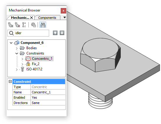
- Directions: specifies whether the directions of the constraint arguments are Same or Opposite. Changing from one to another flips constrained entities with respect to each other.
Direction is used for lines, planes, circles, cylinders, cones and tori. It is not used for points and spheres.
The direction of a plane is its normal vector. The direction of a circle is the normal vector of the circle's plane. The direction of a cylinder, cone, or torus is the direction of its axis. The direction of a planar face of a 3D solid is additionally adjusted to be external with respect to the 3D solid object.
Any option means that the directions may change upon direct modeling operations or upon a 3D constraint parameter change.
The Keep option forces BricsCAD® to keep the current directions. This option forces BricsCAD® to analyze the mutual location of the arguments prior to 3D constraints solving and use either Same or Opposite (not both).
- Placement: specifies how to place an argument with respect to another argument of the same constraint. For example, a point in a point-sphere distance may be placed either Outside or Inside of a sphere. Changing this property for a constraint argument moves the argument to the other side of another argument. The sides are defined for planes, spheres, cylinders, cones, and tori. And not defined for points, lines, and circles.
Any means that both Outside and Inside placement is suitable for user's intentions.
Keep option forces BricsCAD® to keep the current placement of the argument. In other words, this option forces BricsCAD® to analyze the mutual location of the arguments prior to 3D constraints solving and use either Outside or Inside (not both). The Keep option is used by default.
- Use as: this property is assigned to the arguments of the Distance and Concentric constraints and applies to circles, spheres, cylinders, cones and tori and defines which geometry is used in a 3D constraint to measure the distance or to coincide with the other entity.
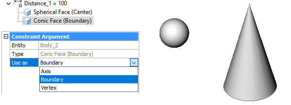
There are four options for the Use as property:
- Boundary: the constraint is applied to the boundary of the argument.
- Axis: applies to an argument that has an axis: circle, cylinder, cone, or torus.
- Center: applies to an argument that has a central point: circle, sphere, or torus.
- Vertex: applies to a cone vertex only.
Context menus
In the Mechanical Browser panel, the following context menus are available.
Main Node
- Add new parameter: creates a new parameter.
- Collapse All: collapse all nodes.
- Expand All: expand all nodes.
Sub-nodes
- Delete: deletes the selected parameter from file.
- Create design table: creates a design table to drive parametric block parameters.
- Animate: animates the parameter value within some range in the drawing.
- Link to parameter: links a subcomponent parameter to the main level parameter.
- Enabled: controls whether the constraint or parameter is evaluated or not.
- Geometry driven: if selected, disables the Expression property. The value of a parameter value is obtained from the model and can be changed with direct modeling operations.
- Flip Side: allows you to change the relative position of an entity (vectors normal of the selected faces point in the same direction or in the opposite direction). This option can be applied to Parallel, Coincident and Concentric constraints only and on condition the constraint is applied to faces.
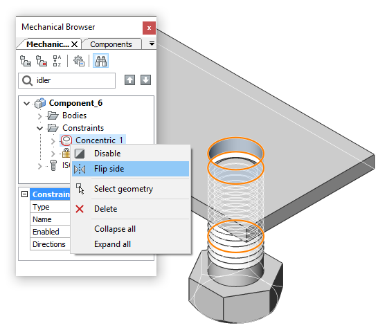
- Select geometry: selects the geometry that is affected by the constraint, in the drawing.
The Parameters Manager panel
The Parameters Manager panel allows you to browse and manage global parameters of your model in tabular form. Every row in this table corresponds to one global parameter, while every column represents a particular property of a parameter - name, expression, value.
In the Parameters Manager panel you can:
- Create a new parameter.
- Delete an existing parameter.
- Click a parameter name field and change it.
- Click a parameter expression field and change it.
- Search a parameter by name.
- Sort all parameters by name, expression, and value.
- Hide all parameters except those relevant to the selected parameter.
- Hide all parameters except those dependent on the selected parameter.
- Animate a parameter.
- Clean unused variables.