


Fuzzy insert guided workflow
Introduction
The reference curves are specific entities of a 2D parametric block. They are used to align the block with entities in the target drawing.
The reference curves can be parametrized. This means that not only the block can be aligned to the entities in the target drawing but also the size and appearance of the block can be adjusted to match the configuration of the entities in the target drawing.
The process of inserting a block with parametrized reference curves into a drawing is called fuzzy insert guided.
Workflow
The workflow of a fuzzy insert guided process is as follows:
- Create a new drawing for the block definition.
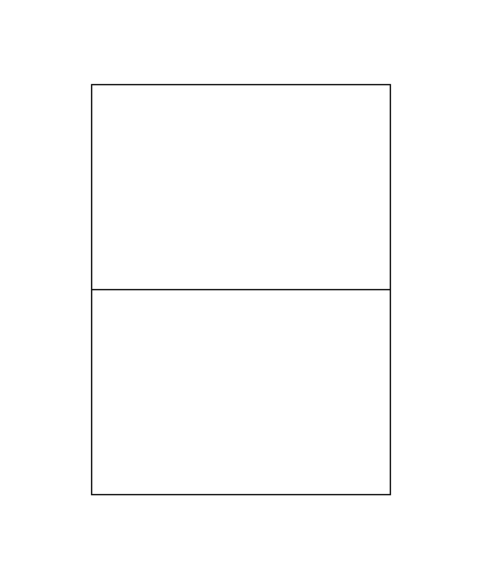
- Create the entities of the block. In this case, a simple rectangular symbol will be used. See the picture below:
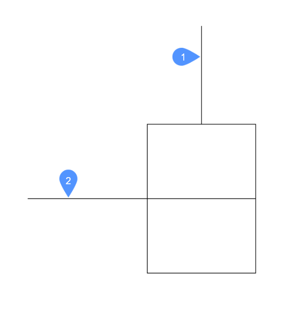
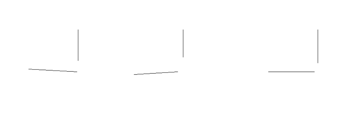
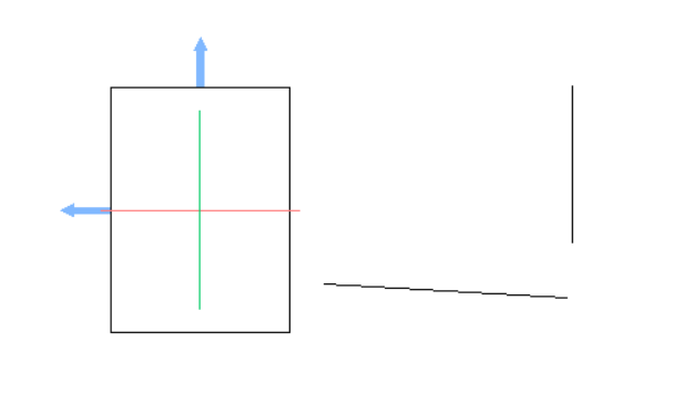
- Create the entities to be used as reference curves, as in the picture below. In this case, the lines marked with 1 and 2 are added and they will be used in the next step.
- Define the reference curves. These curves are not part of the detail curves but will be used as a reference for the insertion (i.e., reference curves).The lines marked with 1 and 2 (from the previous step) will be converted into reference curves using the REFERENCECURVES command. This command can be launched by typing REFERENCECURVES in the command line or by using the Reference Curves button in the Operations tab in the ribbon.To define the reference curves, launch the REFERENCECURVES command and select lines 1 and 2.After running the command, the drawing will look like this:
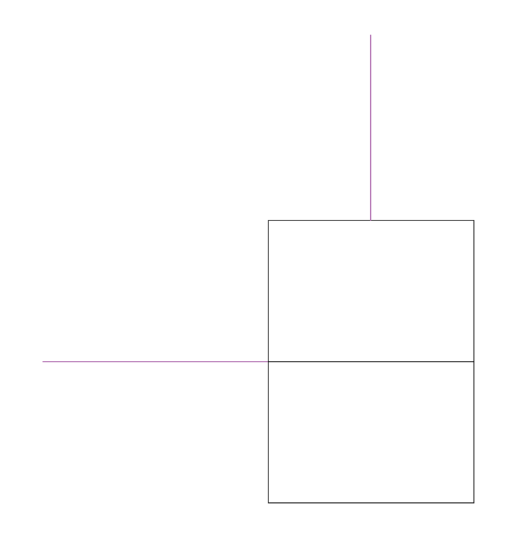 The two lines have been converted into reference curves. Their color has been changed to purple and they have been moved to a special layer, named REFERENCE_CURVES. This layer is created automatically by the command.
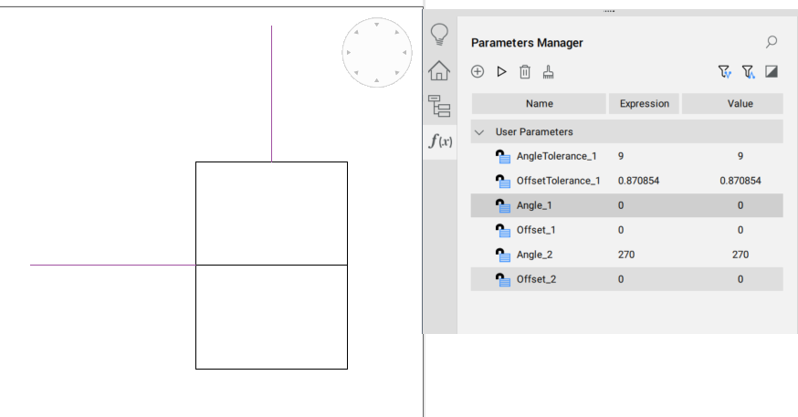
 - To parametrize the reference curves, run the REFERENCECURVES command and select the PARAMETRIZE option. This option will create parameters, controlling the reference curves configuration. These parameters can now (optionally) be used in the expressions of manually added constraints (for example, to fix the reference curves to the detail entities).The parameters can be viewed in the Parameters Manager panel, as in the picture below.
- Save the block.
- Open the target drawing and insert the block.The fuzzy insertion behavior can be achieved by using the INSERT command (with the Use reference curves for insert option On in the Insert Block dialog box), or by drag and dropping a block with parametrized reference curves from the library into the current model space.The reference curves of the block should be correctly tweaked and mapped to the target situation. Move the mouse to a position where you want to snap it and click to place the block.Here is a simple drawing used to see how fuzzy insert guided works:
After running the INSERT command (with the Use reference curves for insert option On in the Insert Block dialog box) the block will be loaded to the mouse cursor.
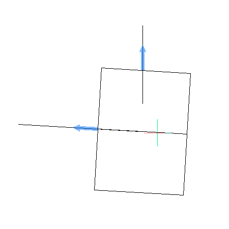
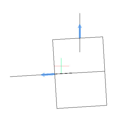
When the mouse cursor is placed near some entities in the drawing, which can match the reference curves, then the block will snap to those entities, like in the pictures below:
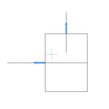
When the mouse cursor (with the block attached) is not around any entities or the entities do not match the reference curves, the snapping behavior does not occur, like in the picture below:
In this case, the block can be inserted into the drawing in a normal way.