The Status Bar
To display the Status Bar, do one of the following:
- Move the cursor over a docked toolbar, the ribbon or a panel icon, then right-click and choose Status Bar in the context menu.
- Press the Shift + F3 keyboard shortcut.
The Status Bar closes if it was open, and vice versa.
The new Status Bar
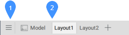
By default, the new Status Bar is enabled (USENEWSTATUSBAR system variable value is On). It displays the Model and Layout tabs (1) and the Status Bar section (2) in one line.

- Model and Layouts tabs
- Status Bar section
- Model and Layouts tabs
- Displays the Model and Layout tabs.
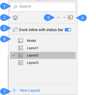
- Manage Model and Layouts menu
- Model and Layout tabs
- Manage model and layouts menu
- Opens the manage model and layouts menu that allows you to create, copy and delete layouts.
- Model and Layout tabs
- Displays the Model and Layout tabs. Right-click a layout to open a context menu with the following options:
- New Layout
- Creates a new layout and adds it at the end of the tabs list.
- From template
- Creates a new layout from a template file chosen from the Select Template From File dialog box.
- Delete
- Deletes the layout.
- Rename
- Renames the layout.
- Copy
- Makes a copy of the layout and adds it after the layout in the tabs list.
- Status Bar section
-

- Visible field
- Drop-down button
- Status Bar menu
Click a field in the Status Bar (1) to toggle it ON/OFF. Right-click a field or click the drop-down button (2) to display a context menu or settings for that field. Hover over a field to display the name and its description. For the narrow BricsCAD windows, fields are displayed as icons.
- Visible fields
- Displays the visible fields of the Status Bar. Click the field to toggle it ON/OFF. Right-click some of the fields to open a context menu with the Setting or Customize options.
- Drop-down button
- Displays a pop-up list of options for the field.
- Status Bar menu
- Displays the Configure Status Bar list of available fields for the Status Bar. Click an item in the list to toggle the display of the corresponding field in the Status Bar. The position of a field in the Configure Status Bar list corresponds to the position of the field in the Status Bar. Customization and settings options are available for each field in the Status Bar, either from the drop-down button or by right-clicking.
Available fields in the Status Bar
- Cursor Coordinate Values
- Displays the coordinates of the current cursor position (depending on the value of the COORDS system variable).
Click the field in the Status Bar to open a context menu. It allows you to change the linear units, and coordinate settings.
- GIS Coordinate System
- Displays the name of the current GIS coordinate system.
- Paper/Model
- Allows you to switch between Model Space and Paper Space or viewports or layouts.
- When working in Model Space, the field reads:
Tile (= Model space with tiled viewports).
Click to switch to the most recently opened paper space layout.
- When working in a layout, the field reads:
M:Layout: Model space with floating viewports
or
P:Layout: Paper space
Click to toggle between paper space and model space with floating viewports.
- When working in Model Space, the field reads:
- Current Layer
- Displays the name of the current layer.
- Click to open a pop-up list with all available layers.
- Click to select the current layer in the pop-up list.
- Click the buttons to toggle each layer property.
- Current Color
- Displays the current color.
- Click to open a pop-up list with colors options.
- Click to select the current color in the pop-up list.
- Click the Select color option to open the Color dialog box.
- Current Linetype
- Displays the name of the current linetype.
- Click to open a pop-up list with the linetypes options.
- Click to select the current linetype in the pop-up list.
- Click the Load option to open the Load Linetypes dialog box.
- Click the Properties option to open the dialog box.
- Current Text Style
- Displays the name of the current text style.
- Click to open a pop-up list with the text styles options.
- Click to select the current text style in the pop-up list.
- Click the Properties option to open the dialog box.
- Current Dimension Style
- Displays the name of the current dimension style.
- Click to open a pop-up list with the dimension styles options.
- Then, click to select the current dimension style in the pop-up list.
- Also, click the Properties option to open the dialog box.
- Grid
- Indicates the status of the GRIDMODE system variable.
- Click to toggle the display of grid in the current viewport.
- Right-click and choose Settings in the context menu to edit the Snap and Grid settings.
- Snap
- Indicates the status of the SNAPMODE system variable.
- Click the field to toggle SNAPMODE On/Off.
- Click the drop-down button and click to select the current SNAPTYPE system variable option in the pop-up list.
- Click the drop-down button and choose Settings in the pop-up list to edit the Snap and Grid settings.
- Dynamic Input (DYN)
- Indicates the status of the DYNMODE system variable.
- Click to toggle the display of Dynamic Dimensions On/Off.
- Ortho
- Indicates the status of the ORTHOMODE system variable. Turning on Ortho automatically disables Polar.
- Click to toggle ORTHOMODE On/Off.
- Right-click and choose Settings in the context menu to edit the ORTHOMODE system variable.
- Polar
- Toggles the Polar Tracking option of the AUTOSNAP system variable.
- Click to toggle Polar Tracking On/Off. Turning on Polar automatically disables Ortho.
- Click the drop-down button and click to select the current POLARANG system variable options in the pop-up list.
- Click the drop-down button and choose Settings in the pop-up list to edit the Polar Tracking settings.
- STrack
- Indicates the status of the Entity Snap Tracking option of the AUTOSNAP system variable.
- Click to toggle Entity Snap Tracking On/Off.
- Right-click and choose Settings in the context menu to edit the Snap Tracking settings.
- ESnap
- Indicates the status of the Entity Snap option of the OSMODE system variable.
- Click to toggle Entity Snaps On/Off.
- Click the drop-down button to open the Entity Snapping Settings pop-up list and click to enable the Entity Snaps options.
- Choose Settings in the pop-up list to edit the 2D and 3D Entity Snaps settings.
- Lineweight (LWT)
- Indicates the status of the LWDISPLAY system variable.
- Click to toggle the display of line weights On/Off.
- Selection Cycling
- Indicates the status of the SELECTIONCYCLING system variable.
- Click to toggle the display of Selection Cycling On/Off.
- Click the drop-down button and click to select the current SELECTIONCYCLING system variable options in the pop-up list.
- Click the drop-down button and choose Settings in the pop-up list to edit the Selection cycling settings.
- Dynamic UCS (DUCS)
- Indicates the status of the UCSDETECT system variable.
- Click to toggle the UCSDETECT system variable On/Off.
- Click the drop-down button and click to select the supported entity types in the pop-up list:
- DUCS on Faces of 3D Solids: 3D solid faces and regions.
- DUCS on Other Entities: 2D linear entities.
- Click the drop-down button and choose Settings in the pop-up list to edit the UCS detect settings.
- AutoScale
- Indicates the status of the ANNOAUTOSCALE system variable. When On, annotative entities are synchronized with the current annotation scale. Click the field to toggle ANNOAUTOSCALE On/Off.
- Annotation Scale
- Displays the value of the CANNOSCALE (= current annotation scale) system variable. Click the drop-down button to open the pop-up list:
- Select an annotation scale in the list.
- Custom: opens the Edit Scale List dialog box.
- Hide Xref scales: lists annotation scales of the current drawing only.
- Annotation monitor
- Indicates the status of the ANNOMONITOR system variable.
- Click to toggle the ANNOMONITOR On/Off.
- Right-click and choose Settings in the context menu to edit the Annotation monitor settings.
- Viewport Lock (VPLOCK)
- Displays the status of Display Locked property of the current viewport or the selected viewport(s). Click the VPLOCK field to toggle the property On/Off.
The VPLOCK field only appears when one or more paper space viewports are selected or when a viewport is active (Model space with floating viewports).
- Viewport Standard Scale
- Allows you to conveniently set the scale of the selected layout viewport relative to paper space.
- Tablet
- Initializes the use of a drawing tablet.
Right-click and choose Settings in the context menu to edit the Tablet mode settings.
- Quad
- Indicates the status of the QUADDISPLAY system variable.
- Click to toggle the display of the Quad On/Off.
- Click the drop-down button and click to select an option in the pop-up list.
- Show Quad on Hover
- Show Quad on Select
- Show Quad on Right Click
- Suppress Quad on Hover When Entities are Selected
- On/Off
- Customize Quad Items…: Displays the dialog box
- Settings…: Displays the Settings - Quad display dialog box
- Rollover tips (RT)
- Indicates the value of the ROLLOVERTIPS system variable.
- Click to toggle the display of rollover tips.
- Click the drop-down button and click to select the available rollover tips display options in the pop-up list:
- Show Rollover when Hovering Entities
- No Rollover tips
- Show Block Parameters
- Click the drop-down button and choose Customize… in the pop-up list to open the dialog box. Here you can define which properties are displayed in the Rollover Tips for each entity type.
- Hide/Isolate Entities
- Highlights only when there are hidden objects in the drawing.
- Click the field to open the options:
- Isolate: launches the ISOLATEOBJECTS command.
- Hide: launches the HIDEOBJECTS command.
- Show All: launches the UNISOLATEOBJECTS command.
- Click the field to open the options:
- Hotkey Assistant (HKA)
- Indicates the value of the HOTKEYASSISTANT system variable. When switched On, an assistant widget at the bottom of the screen reveals options available by pressing the Ctrl key.
- Click to toggle the display of the HKA widget On/Off.
- Right-click and choose Configure option in the context menu to display the Hotkey Assistant Configuration dialog box. Select the commands for which you want the HKA widget to display when HOTKEYASSISTANT = ON.
- Current Workspace
- Displays the name of the current workspace.
- Click to set the value of the WSCURRENT system variable in the Command line.
- Click and choose the current workspace in the pop-up list.
- Choose Customize in the pop-up list to open the dialog box.
- Lock User Interface (LOCKUI)
- Allows you to lock the location and size of toolbars and dockable panels.
- Click to toggle the lock On/Off.
- Click the drop-down button to display a pop-up list.
- Select the UI items to lock: toolbars, panels or both.
- Choose Settings… to set the value of the LOCKUI system variable in the Settings dialog box.
- Publish Monitor
- Manages the publishing process. The button is highlighted while publish is in progress.
- Show Notifications
- Toggles the displaying of the notifications.
The old Status bar
Setting the USENEWSTATUSBAR system variable to Off returns the old Status Bar.

- Status field
- Field List button
- Status field
-
- Displays the status of the software.
- When the cursor is in a menu or on a toolbar, it gives a brief description of the tool or menu item under the cursor.
- When the command window is closed, it displays the command prompts, tool options and keyboard entry.
- Double-click the status field to open or close the Command line.
- Field List button
- Click the arrow button (
 ) to display a list of available Status Bar fields. Click an item in the list to toggle the display of the corresponding field in the Status Bar.Tip: Right-click a field to open a context menu with more options.