BIMBEAM command
Creates solids classified as Beam.

Icon: 
Description
The command creates beams with different shapes. You can define the options through the command context panel, as well as through the Command line.
Method
Launch the command to open the Beam command context panel.
Note: To place beams more easily, enable Top View Mode (TVM) before launching the command by clicking a story disk ( ) in the Story Bar (see The Story Bar article). Make sure the top section plane is placed above the beam.
) in the Story Bar (see The Story Bar article). Make sure the top section plane is placed above the beam.There are two methods to create beams:
- Place single beams, constrained by the X-/Y- axis
- Draw poly beams, unconstrained by the X-/Y- axis
Use the dynamic dimensions to define the insertion point of a single beam more accurately. These dimensions show the distances from the single beam to walls and/or beams. Tap the TAB key to switch between dimensions and set them manually.
Note: Dynamic dimensions are displayed if Dynamic
Input (DYN) is set to
On (see Dynamic dimensions article).
Use the Hotkey Assistant widget to change the direction of the current single beam. Press the Ctrl key to switch between options X-aligned beam and Y-aligned beam.

Note: The Hotkey Assistant widget is displayed if the HOTKEYASSISTANT system variable is set to 1 and the Display Hotkey Hints for BIMBEAM options check box is ticked in the Hotkey Assistant Configuration dialog box (see Hotkey Assistant widget article).
Options within the command context panel
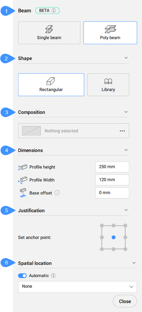
- Creation mode
- Shape
- Composition
- Dimensions
- Justification
- Spatial location
- Creation mode
- Choose a method for creating the current beam/beams.
- Shape
- Defines the current beam profile. You can select an exiting profile or create a new one.
- Composition
- Click the browse button (
 ) to open the Compositions dialog box that lets you define the current beam composition. Here you can change the composition type by selecting a new filter from the top left drop-down menu.
- Dimensions
-
- Profile height/Profile width
- Sets the profile height/width.Note: These options are only available for the Rectangular profile.
- Justification
- There are nine justification points: top left, top center, top right, middle left, middle center, middle right, bottom left, bottom center, bottom right. By default, the anchor point is set to middle center. To change it, click another displayed anchor point.
- Spatial location
- Allows you to select a spatial location from the drop-down menu to assign to the beam.
Note: The options within the command context panel and those within the Hotkey Assistant widget reflect the options within the Command line.