Creates solids classified as Wall.
Icon: 
Description
The command allows you to easily create walls from scratch or detect walls from point clouds, aligned with UCS X- or Y-axis or unconstrained by these. You can define the options through the command context panel, as well as through the Command line.
Method
Launch the command to open the Wall command context panel.
Note: To place walls more easily, enable
Top View Mode (
TVM) before launching the command by clicking a story disk (

) in the
Story Bar (see
The Story Bar article).
Select a mode to create walls:
- Place single walls, constrained by the X-/Y- axis, or by a fixed angle.
- Draw poly walls, unconstrained by the X-/Y- axis.
- Select entities in the drawing to extrude as walls.
In
Single wall mode, the current wall automatically extends to any wall that is visible in the current view. The result can thus be a wall with:
- both ends attached to other walls.
- only one end attached to another wall, while you can dynamically specify the length of the current wall.
- none of the ends attached to other walls, while you can set a value in the Free wall length field.
Use the Hotkey Assistant widget to change the direction of the current single wall. Press the Ctrl key to switch between the displayed options.
Note: The Hotkey Assistant widget is displayed if the HOTKEYASSISTANT system variable is set to 1 and the Display Hotkey Hints for BIMWALL options checkbox is ticked in the Hotkey Assistant Configuration dialog box (see Hotkey Assistant widget article).
Use the dynamic dimensions to define the insertion point more accurately. These dimensions show the distances from the current single wall to other, parallel, walls. Tap the Tab key to switch between dimensions and set them manually.
Note: Dynamic dimensions are displayed if Dynamic Input (DYN) is set to On (see Dynamic dimensions article).
Use the selection dimensions to reposition the selected wall relative to the nearest detected walls and/or columns or other convenient reference points (see Selection dimensions article).
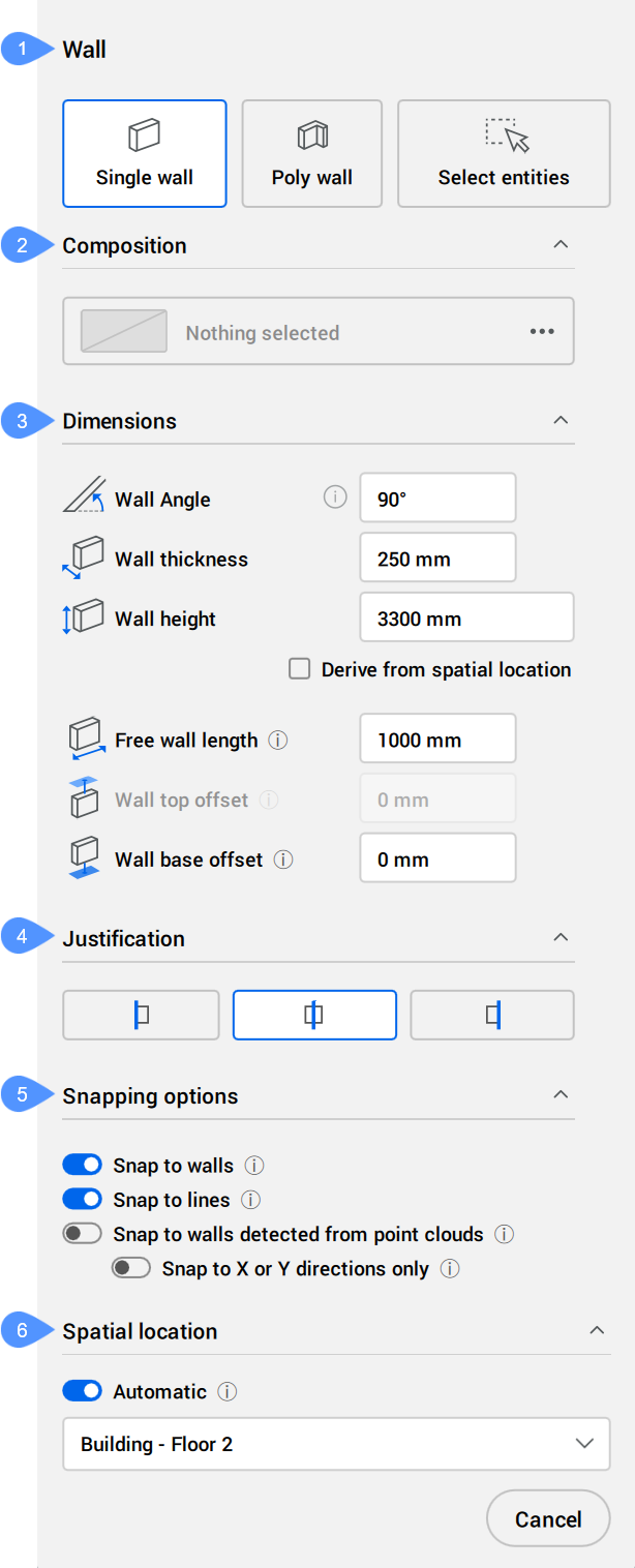
Options within the command context panel
- Creation mode
- Composition
- Dimensions
- Justification
- Snapping options
- Spatial location
- Creation mode
- Allows you to choose a mode for creating the current wall/walls.
-
- Single wall
- Creates X-aligned or Y-aligned single walls.
-
- Poly wall
- Creates a polyline shaped wall, unconstrained by the X- or Y-axis. You can define the new wall by manually drawing a polyline.
-
- Select entities
- Allows you to select polylines in the drawing from which to create the new walls.
- Composition
- Click the browse button (
 ) to open the Compositions dialog box that lets you define the current wall composition. By default, the compositions of type Wall are shown. You can change this filter in the Compositions dialog box.
- Dimensions
- Allows you to define the dimensions of the current wall.
-
- Wall angle
- Sets the direction of the current wall. Only available for Single wall mode.
-
- Wall thickness
- Sets the thickness of the current wall.
-
Note: When a composition with a fixed or minimal thickness is selected, the thickness input field is constrained accordingly.
-
- Wall height
- Sets the height of the current wall.
-
- Derive from spatial location
- If checked, deactivates the Wall height field and uses the information from the Spatial Locations Manager dialog box.
-
- Free wall length
- Sets the length of the current free wall. Only available for Single wall mode.
-
- Wall top offset
- Sets the top offset from the slab detected above the current wall.
-
- Wall base offset
- Sets the base offset from the slab detected below the current wall.
- Justification
- There are three justification options: left, center and right. By default, the justification is set to center. To change it, click another justification option.
- Snapping options
- Turns on/off multiple wall snapping options. Only available for Single wall mode.
-
- Snap to walls
- Snaps the wall cursor to existing walls and wall extensions.
-
- Snap to lines
- Snaps the wall cursor to existing lines, both single and double. For double lines, their distance will be adopted as the wall thickness.
-
- Snap to walls detected from point clouds
- Snaps the wall cursor to nearby walls detected from an underlying point cloud and adopts their thickness and direction.
Note: When snapping to external walls, the thickness of the current wall is defined by the value specified in the Wall thickness field.
-
- Snap to X or Y directions only
- Constrains the snapping directions of the current wall to X- or Y- axis.
-
Note: The order in which snapping options are present in the command context panel represents their application hierarchy.
- Connections
-
- Connect to snapped walls
- In Poly wall mode, controls whether the Poly wall's start and end will be connected to snapped walls (mitered connection).
- Spatial Location
- Accept the automatically assigned spatial location or define a new one by selecting an option from the drop-down menu.
-
- Automatic
- Copies the spatial location of the closest underlying slab.
-
Note: Selecting a different spatial location than the one automatically assigned switches off the Automatic option.
Note: The options within the command context panel and those within the Hotkey Assistant widget reflect the options within the Command line.