BLOCK command
Opens the Create Block Definition dialog box.

Icon: 
Alias: B
Description
Opens the Create Block Definition dialog box to create a block definition in the current drawing.
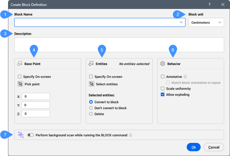
- Block Name
- Block unit
- Description
- Base Point
- Entities
- Behavior
- Perform background scan while running the BLOCK command
Block Name
Specifies the name of the block.
Block unit
Scales the block correctly when the block definition is inserted in a drawing whose units are different from the drawing in which the block was created. More specifically, in which the INSUNITS variable differs.
Description
Provides a description of the block (optional).
Base Point
Modifies the properties of the base point of the block definition. At this point, the block is inserted with the INSERT command.
- Specify On-screen
- Allows you to define the base point in the model space after you click the OK button, if the box is ticked.
- Pick point
- Allows you to pick a point in the drawing for the block's base point. You can also enter the X,Y,Z coordinates in the drawing.
- X/Y/Z
- Defines the coordinates where the block should be inserted. The Z coordinate is usually optional.
Entities
Selects the entities that make up the block.
- Specify On-screen
- Allows you to select the entities in the model space after you click OK, if the box is ticked.Note: Optionally, include Reference Curves in the selection, which allows to automatically align a block during insertion.
- Select entities
- Selects one or more entities in the drawing.
- Selected entities
- Defines how the entities are turned into a block.
- Convert to block
- Selected entities are converted to a block. This is the default option.
- Don't convert to block
- Selected entities are retained as entities, and the block definition is created in the drawing.
- Delete
- Selected entities are deleted after the block definition is created.
Note: The Convert to block option is the most efficient one.
Behavior
- Annotative
- Sets the annotative property of the block. This type of block should be created when the annotation scale in model or paper space is 1:1. By being annotative, the block automatically scales itself according to the current annotation scale factor.Choose whether you want the block to follow annotative scaling:
- On: the block will scale itself to whatever annotative scale is in effect. The Scale Uniformly option is grayed out (unavailable).
- Off: the block follows the scale factor you give the block during the INSERT command.
Note: You can modify supported annotation scales of a selected block attribute in the Properties panel, even when its owning block reference is not annotative.- Match block orientation to layout
- Determines if annotative blocks match the orientation of the layout.
- On: annotative blocks display upright, regardless of the orientation of the viewport.
- Off: annotative blocks match the orientation of the viewport.
- Scale uniformity
- Determines if blocks can be scaled non-uniformly. This option is not available to annotatively-scaled blocks.
- On: X, Y, and Z scale factors of blocks are the same. This prevents blocks from being distorted.
- Off: blocks can be inserted with different X, Y, and Z scale factors. This is useful for objects that can have different dimensions, such as differently sized table tops.
- Allow exploding
- Determines if users can explode the block after it is inserted. When a block is exploded, it loses its block status, and the individual entities can be edited.Tip: To edit the entities of an unexploded block, use the BEDIT command.
- On: blocks can be exploded after being inserted, using the EXPLODE command.
- Off: blocks cannot be exploded. You can change this property with the EXPBLOCKS command, Blocks section.
Perform background scan while running the BLOCK command
If turned On and the Convert to block option is selected, it checks whether the selection has matching entities in the drawing and whether a block definition already exists for the selection.
If turned Off, it cancels the background scan.
Changes the value of the BLOCKIFYSCANNER system variable.
- Run Blockify
- Displays if duplicates of the block are found in the drawing for the selected entities.
Opens the Blockify command context panel to convert the selection and all similar entities to the new block definition.
- Reuse block definition
- Displays if an existing block definition is found in the drawing for the selected entities.
Converts the selection to block instances of the existing block definition.
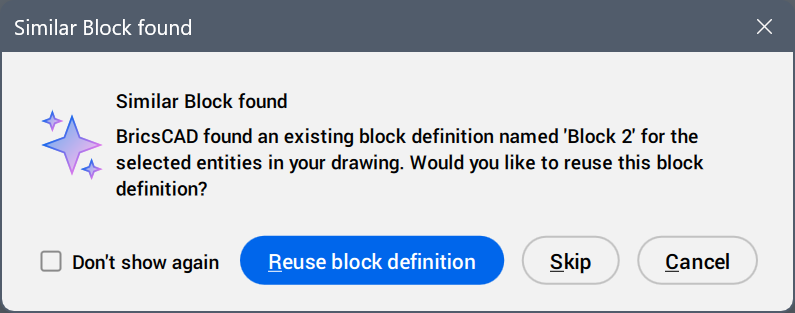
- Skip
- Creates the new block definition and ends the command.
- Cancel
- Returns to the Create Block Definition dialog box.