BMEXPLODE command
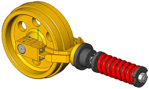
Creates a block with a representation of the current assembly.

Icon: 
Description
Creates a block with a representation of the current assembly. This block can be inserted at any location.
- Local mechanical blocks based on blocks and solids, and mechanical block external references are fully supported in exploded views.
- Non-mechanical entities are also supported, making it possible to create exploded views without creating a mechanical assembly first.
Method
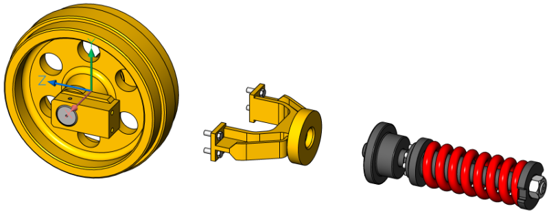
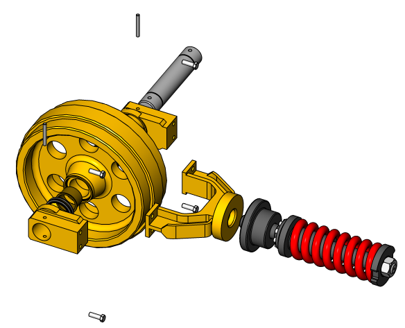
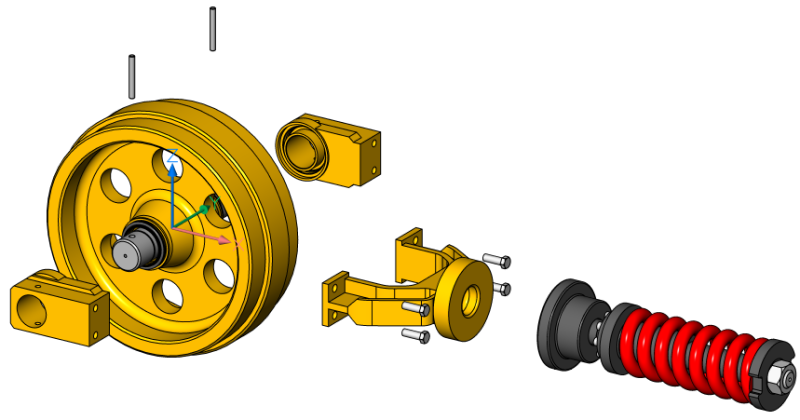
You can create an exploded view using the entire model as selection set or specify a set of parts to create an exploded view from.
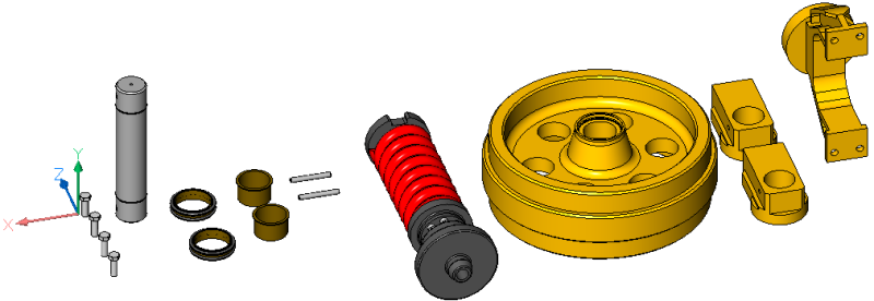
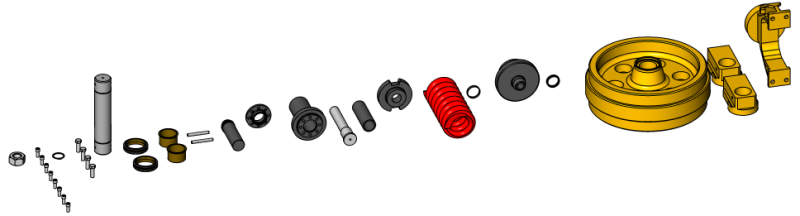
Two levels of the representation are supported: top and bottom. Top-level means that the assembly will be exploded down to top level components. Bottom-level means that the assembly will be exploded down to bottom level components.
The steps to create a representation are automatically completed and are displayed in the Mechanical Browser panel. You can add, delete and reorder the steps from the Mechanical Browser panel. Animate a single step of an explosion or the entire sequence.
Options within the command
- Table by types
- Groups identical parts on the same row and different parts on different rows.
-

- Linear
- Automatically creates representations of assemblies in a given direction, taking into account possible physical collisions between components.
-
- Automatic
- Automatically determines the directions for each part, taking into account possible physical collisions between components.
-
- Auto
- Enables automatic gap calculation.
-
- Manual
- Selects the manual mode. This creates an exact copy of the assembly, ready to create a customized exploded view.
-
- Update
- Updates solids and block references in exploded view block with model space objects.
- Convert to new format
- Converts old format representation to the new one.Note: This option is available only when there are old format representations in the drawing.
- Settings
- Gives access to the command settings.
-
- Top
- If selected, the assembly will be exploded using only top-level components.
-
-
- Bottom
- If selected, the assembly will be exploded down to bottom-level components.
-
- Edit
- Opens the representation for editing.Note: This is the default option.
- Generate drawing views
- Generates drafting views from a representation.
- Finish
- Concludes the command.