Weld Symbol dialog box
Opens via: AMWELDSYM command
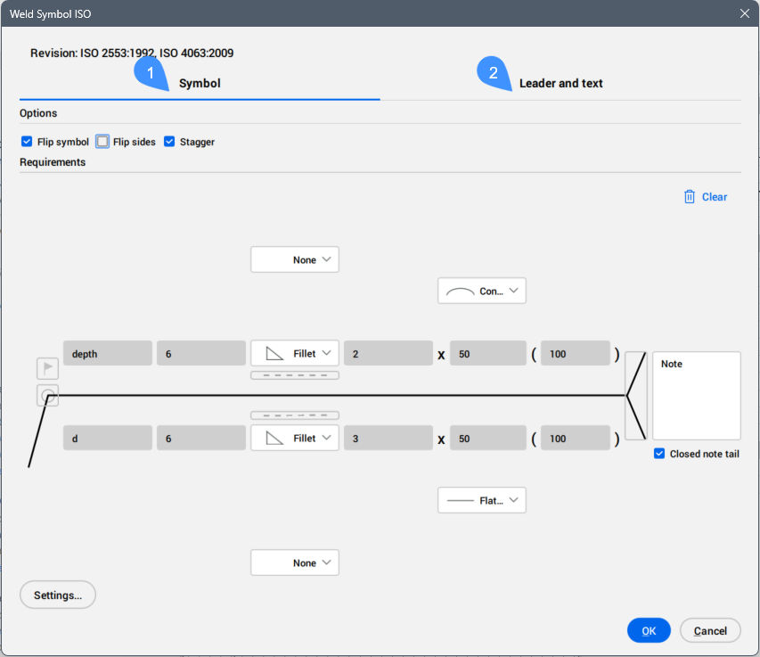
The Weld Symbol dialog box allows you set the default weld symbols for the current drafting standard.
The parameters entered for the weld symbols are stored temporarily and used as default values for the next weld symbols setting.
The most recent revision of the standard to which this symbol conforms is displayed at the top of the dialog box.
The dialog box contains 2 main tabs, Symbol and Leader and text.
- Symbol
- Leader and text
Symbol
Specifies the weld symbol characteristics.
Important: The available parameters depend on the type of weld and the standard to which this symbol complies. After creating a weld symbols, you are able to edit their parameters in the Weld Symbol dialog box or in the Properties panel.
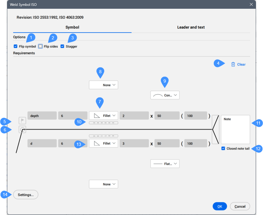
- Flip symbol
- Flip sides
- Stagger
- Clear
- Field weld
- All around
- Weld type for current process for the other side
- Weld type for second process for the other side
- Contour
- Identification line
- Process notes
- Closed note tail
- Weld requirements for the arrow side
- Options
-
- Flip symbol
- Specifies whether the symbol is aligned to the right or left.
- Not ticked: aligns to the right.
- Ticked: aligns to the left.
- Flip sides
- Swaps the symbol and its parameters on the arrow side with the symbols on the other side.
- Stagger
- Specifies whether the weld is a staggered intermittent weld. Available only if you select fillet welds or ANSI edge welds for both sides.
- Requirements
-
- Clear
- Clears the last inserted parameters. The cells become empty.
- Field weld
- Toggles the visibility of the Field weld symbol in the current operation. When ON, indicates that welding must be performed in the field during the erection of the structure.
- All around
- Toggles the visibility of the All around symbol (continuous weld) in the current operation.
- Weld type for current process for the other side
- Allows you to choose the weld type from the drop-down list. Each weld type is accompanied by a symbol that represents a simplified cross-section of the weld.
Depending on the type of weld and the standard to which this symbol complies, you can define the weld parameters. Hovering over a field gives you the description of the parameter.
- Depth
- Defines the depth of the weld.
- Size
- Defines the size of the weld.
- Number
- Defines the number of welds.
- Length
- Defines the length of the weld.
- Spacing
- Defines the distance between welds.
- Weld type for second process for the other side
- Allows you to define additional weld type and parameters for the current process.
- Contour
- Allows you to choose the finishing contour of the weld surface from the drop-down list.
- Identification line
- Displays the identification line.
- Process notes
- Adds note that specifies the welding requirements.
- Closed note tail
- Draws a box around the tail note.
- Weld requirements for the arrow side
- Allows you to define the weld type and parameters for the arrow side, similar to the weld type for the other side.
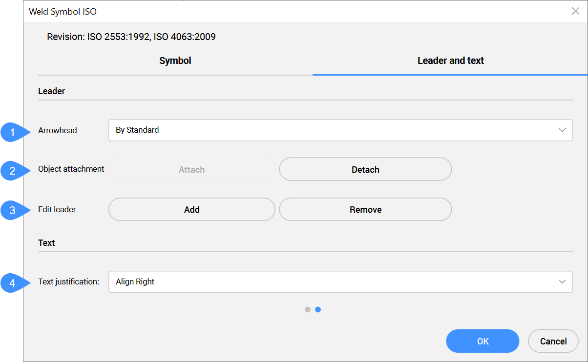
Leader and text
Specifies the leader and text characteristics.
- Arrowhead
- Object attachment
- Edit leader
- Text justification
- Leader
-
- Arrowhead
- Defines the default arrowhead type for welding symbols.
- Object attachment
- Defines if the symbol leader is attached or detached to the object.
- Attach
- Attaches the symbol to the selected object.
- Detach
- Detaches the symbol from the object.
- Edit leader
- Edits leader segments.
- Add
- Adds new leader segments or leader nodes.
- Remove
- Removes leader segments or leader nodes.
- Text
-
- Text justification
- Specifies whether the symbol text is aligned to the right, center or left.