Direct modeling operations
Controlling the coordinate system
Since entities are created in the XY-plane of the current coordinate system (UCS), it is necessary to align the UCS with the 3D solid face. You have two options here:
- The Align UCS tool (
 ) launches the UCS command with the Face option selected.
 - Click the DUCS field in the Status Bar to toggle the dynamic UCS feature ON and OFF. When ON, the UCS aligns automatically to the solid face under the cursor when executing a command and the UCS-icon changes accordingly. Press the Tab key to select an obscured face. Press the Shift key to temporarily lock the UCS, which allows you to work outside the hovered entity or face. Press the Shift key again to unlock it.
Selecting geometry
- Hit the Tab key to select obscured geometry.
- The SELECTIONMODES system variable controls which subentities highlight: edges, faces, and/or closed boundaries. Hold down the Ctrl key to overrule SELECTIONMODES, and select the subentity under the cursor.
- Window selection: to select the faces or edges of 3D solids and surfaces, press the CTRL key to cycle the options. The icon next to the cursor indicates what will be selected.
- The DMSELECT command allows you to select edges and faces based on their geometrical and topological properties:
- Edges of a particular length.
- Edges that form a concave/convex network.
- Edge loops on the border of a set of connected faces.
- Faces of a particular area.
- Smoothly connected faces (G1 - tangent faces, or G2 - curvature continuity).
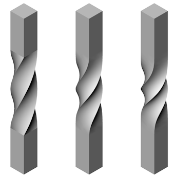
G0: No continuity (left), G1: Tangent Faces (middle), and G2: Curvature continuity (right)
- Fillets of a specific radius.
- Cylindrical protrusions of a specific radius.
- Protrusion or depression features; pockets, extrusions, or ribs.
The value of a particular length, area, or radius can be taken from a selected edge/face.
Moving faces to control dimensions
A dynamic dimension displays with the DMPUSHPULL command.
Make sure the Quad and Dynamic Dimensions are switched ON.
- Hover the cursor over the face you want to move.
The face highlights.
- Choose Push/Pull (
 ) in the Model tab of the Quad.
The selected face moves with the cursor and a dynamic dimension field displays the relative distance along with a ruler.
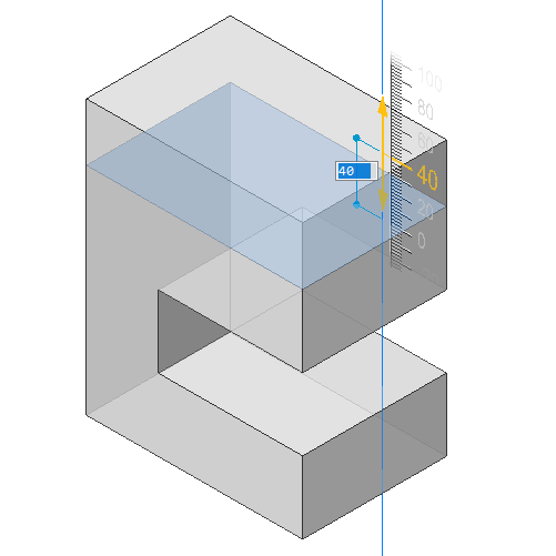
When the cursor is on the ruler, the face moves with fixed intervals. Zoom in or out to increase or decrease the interval.
When the cursor is outside the ruler, the face moves freely.
- (Option) repeatedly hit the Tab key to see the distance with respect to an internal face, parallel to the selected face (left) or the bottom face (right).
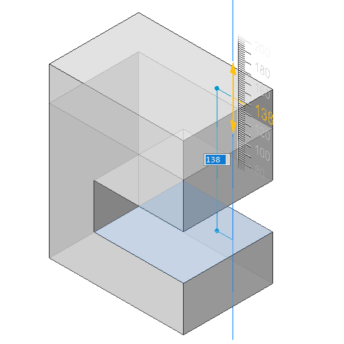
Press and hold the Shift key and hit the Tab key to reverse the display order of reference faces.
- Do one of the following.
- Type a value in the dynamic dimension field, then hit Enter.
- Using the ruler: click when the desired value displays.
Making holes
Method 1:
- Create the subtractor solid.
- Use the SUBTRACT command.
Depending on the value of the DELETETOOL system variable, the subtractor solid is either deleted or retained.
Method 2:
- Create the outline of the opening on the 3D solid face.
- Place the cursor over the outline, then choose Solid Extrude (
 ) (DMEXTRUDE command) in the Model tab of Quad.
 - Move the cursor inside the solid to make the opening.
- Do one of the following:
- Specify a point.
- Type a value.
To make a hole in a surface
- Create a 2D closed entity, e.g. an ellipse.
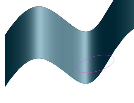
- Place the cursor over the 2D closed entity, then choose Solid Extrude (
 ) (DMEXTRUDE command) in the Model tab of Quad.
 - Extrude the 2D entity in the direction of the surface.
The default extrusion direction is perpendicular to the plane of the 2D entity.
The Hotkey Assistant (HKA) appears at the bottom of the screen.
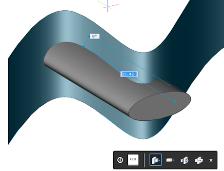
- Hit the CTRL key twice to select the Subtract option of the DMEXTRUDE command.
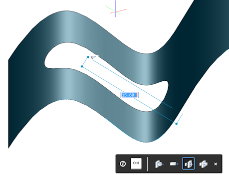
- Click to create the opening.
Deleting features
The Feature option of the DMSELECT command allows to easily select all faces of a hole, depression or protrusion.
In the Mechanical workspace, the Protrusion and Depression tools are available in the Select panel of the Modeling ribbon tab and the Select tab of the Quad.
The tools sit in the Sheet Metal toolbox. See Available Tools in the Customize dialog box.
To delete a depression (hole or pocket) or a protrusion feature (extrusion or rib)
- Click the Protrusion (
 ) or Depression (
 ) tool button in the Select panel of the Modeling ribbon tab or from the Select command group of the Quad.
 - Select one or more faces of the feature.
All adjacent faces of the feature are detected.
- Click the Erase (
 ) tool button.
Removing edges between coplanar faces
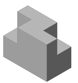
When two or more faces are made coplanar, e.g. with the DMPUSHPULL command, it might be necessary to remove the shared edges using the DMSIMPLIFY command.
 |
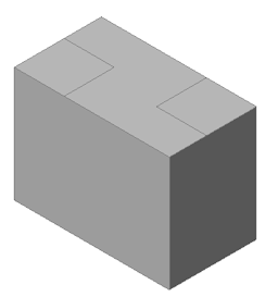 |
| Two depressed faces | Two depressed faces moved to the top face, to create three coplanar faces. |
- +Launch the DMSIMPLIFY command.
You are prompted: Select entities to simplify or [Entire model/SEttings/selection options (?)] <Entire model>:
- Select the solid, then press Enter.
The edges are removed.
Copying a Feature
The DMCOPYFACES command allows you to copy one or more features from a 3D solid (depressions - holes, grooves, and pockets - or protrusions - extrusions and ribs), to a new location on the same or a different 3D solid.
Make sure dynamic UCS is enabled.
- Select all faces of the entire feature(s).
- Click the Copy Faces (
 ) tool:
- on the ribbon: Modeling | Edit | Copy Faces.
- on the Direct Modeling toolbar.
- in the menu bar: Model | Direct Modeling | Copy Faces
- in the Model tab on the Quad
- Specify the base point.
You are prompted: Select an insertion point or [Rotate/mUltiple/MOde]:
- (Optional):
- Use the Rotate option to rotate the faces around the Z axis of the UCS.
- Use the Multiple option to insert the multiple copies of a feature.
- Specify the insertion point.
The feature is copied from the base point to the insertion point with dynamic UCS.
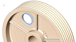
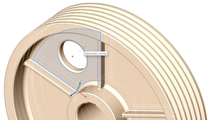
Select the faces of the entire feature Specify base point 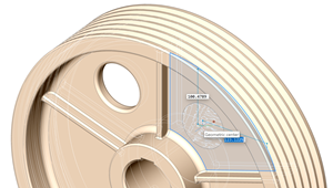
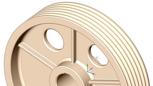
Specify the insertion point The feature is copied
Deformable modeling
Use the tools on the Deform toolbar, to deform a set of adjacent faces on a 3D solid or a surface, to create complex aesthetic shapes.
The faces are always deformed if:
- The external boundary (= edges, which are adjacent to only one of the selected faces) remains unchanged.
- The internal boundaries (= edges, which are adjacent to two of the selected faces) are deformed together with the faces.
- The initial continuity between deformed faces (G1 – tangent faces, or G2 – curvature continuity) is kept when deformed.
For a twist deformation, it is possible to specify the continuity between the deformed and the fixed portion of the entities.
Deformation can be defined in several ways:
- DMTWIST command: Twist the whole entity or a portion.
- DMDEFORMPOINT command: Move a point on a face in any direction in 3D space.
- DMDEFORMMOVE command: Move or rotate one or more edges.
- DMDEFORMCURVE command: Replace an edge with a given 3D curve.

