Komponenty i wstawienia komponentów
Komponent to nazwana grupa elementów, którą można wstawić do rysunku za pomocą polecenia BmWstaw. Komponenty mogą być parametryczne: np. okna i drzwi w BricsCAD BIM oraz standardowe komponenty mechaniczne w BricsCAD Mechanical.
Dowolny plik .dwg może być użyty jako komponent. Ten sam komponent może być wstawiony raz lub kilka razy do jednego lub kilku innych komponentów. Gdy komponent zostanie zmodyfikowany, wszystkie jego wstawienia automatycznie odzwierciedlą te zmiany. Komponenty nie mogą odnosić się do siebie.
Wstawienie komponentu jest nazwanym elementem. Domyślna nazwa wstawienia komponentu składa się z nazwy komponentu i numeru seryjnego wstawienia. Wewnętrznie wstawienie komponentu jest reprezentowane jako odwołanie do anonimowego bloku lub jako odwołanie zewnętrzne.
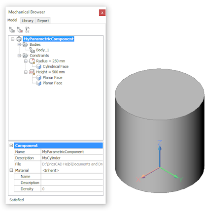
Właściwości wstawionych komponentów, w tym ich parametry, można edytować w panelu Przeglądarka Mechaniczna i panelu Właściwości.
Komponenty zewnętrzne i lokalne
Komponenty mogą być lokalne lub zewnętrzne. Komponent lokalny jest przechowywany w pliku .dwg z złożeniem jako anonimowym blokiem. Komponent zewnętrzny jest zdefiniowany w oddzielnym pliku .dwg i reprezentowany przez Xref lub jako lokalna kopia przechowywana jako anonimowy blok. Gdy odpowiedni plik .dwg jest zmodyfikowany wszystkie wstawienia komponentów zewnętrznych można zaktualizować za pomocą polecenia BMAKTUALIZUJ lub menu kontekstowego Przeglądarki Mechanicznej. Jeśli używasz zewnętrznych komponentów w swoim złożeniu, zawsze pamiętaj o przesłaniu wszystkich powiązanych plików, gdy chcesz udostępnić swój model.
Użyj polecenia ETRANSMIT, aby utworzyć pakiet pliku rysunku i wszystkich jego zależności, takich jak odniesienia zewnętrzne, obrazy, pliki czcionek, pliki konfiguracji wykresu, tabele stylów wykresu i pliki mapy czcionek.
Zawsze można przekonwertować komponent lokalny na zewnętrzny i odwrotnie.
Aby edytować komponent lokalny, należy go najpierw przekonwertować na komponent zewnętrzny za pomocą polecenia BMUZEWNĘTRZNIJ. Alternatywnie można użyć polecenia BMOTWÓRZKOPIĘ, aby otworzyć kopię komponentu, edytować ją i zapisać. Następnie użyj polecenia BMZAMIEŃ, aby zastąpić oryginał kopią.
Można wybrać domyślny typ wstawiania komponentu: Lokalny lub Zewnętrzny. Aby zmienić typ, wybierz węzeł główny w Przeglądarce Mechanicznej i wybierz Lokalny lub Zewnętrzny z Wstaw jako właściwości.
W zależności od wartości BMAUTOUPDATE, wstawienia komponentów zewnętrznych są aktualizowane automatycznie po otwarciu dokumentu złożenia lub ręcznie za pomocą polecenia BMAKTUALIZUJ. Wartość tę można zmienić w oknie dialogowym Ustawienia. Dostępne opcje to:
- Aktualizuj tylko w przypadku użycia polecenia BMAKTUALIZUJ.
- Aktualizuj automatycznie po otwarciu pliku.
Konwersja komponentów
Polecenie BMUZEWNĘTRZNIJ konwertuje komponenty lokalne na komponenty zewnętrzne.
Polecenie BMLOKALIZUJ konwertuje komponenty zewnętrzne na komponenty lokalne.
Wykonaj jedną z następujących czynności:
- Kliknij przycisk Przełącz komponent na zewnętrzny (
 ) lub Przełącz komponent na lokalny na karcie wstążki Złożenie. Narzędzia te są również dostępne na pasku narzędzi Złożenie i w menu Złożenie.
 - Kliknij prawym przyciskiem myszy wstawienie komponentu w Przeglądarce Mechanicznej i wybierz Przełączn na Zewnętrzne lub Przełącz na Lokalne z menu kontekstowego.
- Najedź kursorem myszy na wstawienie komponentu w oknie rysunku i wybierz opcję Przełącz na zewnętrzny (
 ) lub Przełącz na lokalny w grupie poleceń Modelowanie Złożenia w oknie Quad.
Podczas konwersji komponentu zewnętrznego na lokalny, plik .dwg z definicją komponentu nie zostanie usunięty, ale przyszłe zmiany nie będą miały wpływu na złożenie.
Wstawienia komponentów lokalnych ( ) i wstawienia komponentów zewnętrznych (
 ) można zawsze rozróżnić na podstawie ich ikon w Przeglądarce Mechanicznej.
Komponenty Parametryczne
Zmiany parametryczne wstawionych komponentów można wprowadzać na poziomie złożenia. Komponent jest uznawany za parametryczny, jeśli zawiera co najmniej jedno ograniczenie wymiarowe 2D lub 3D lub szyk asocjacyjny z wyrażeniem.

- BricsCAD automatycznie zachowuje asocjatywność między definicją komponentu parametrycznego a jego wstawieniami. W ten sposób można otworzyć komponent parametryczny do edycji, zmodyfikować jego geometrię i zapisać go. Aby zobaczyć wynik, wykonaj polecenie BmAktualizauj, aby zaktualizować strukturę mechaniczną złożenia.
- Jeśli chcesz powrócić do domyślnej wartości parametru komponentu, po prostu edytuj pole Wyrażenie i usuń jego zawartość.
Można kontrolować, czy dany parametr komponentu będzie dostępny do edycji na rysunku zawierającym wstawienia tych komponentów (na poziomie złożenia). Aby to zrobić, wybierz parametr w Przeglądarce Mechanicznej i zmień wartość pola Widoczny w siatce właściwości parametru.
Dostępne opcje to:
- Wył: ukrywa parametry w złożeniu.
- Wł: Sprawia, że parametr jest widoczny na poziomie złożenia.
- Resetuj: Ukrywa wszystkie parametry z wartościami kontrolowanymi przez wyrażenia i ujawnia wszystkie pozostałe parametry.
Z parametrem można powiązać elementy. W przypadku przypisania wartości, bezpośrednio lub za pomocą wyrażenia, do parametru komponentu na poziomie złożenia, następuje automatyczna konwersja z jednostek rysunku złożenia na jednostki parametru. Wartości przypisane do parametrów bez jednostek nie są konwertowane.
Domyślnie wszystkie parametry są bezjednostkowe, z wyjątkiem parametrów ograniczeń wymiarowych i parametrów, które są używane jako wyrażenia dla ograniczeń wymiarowych. BricsCAD automatycznie przypisuje jednostki rysunkowe do takich parametrów.
Aby edytować parametry wstawionego komponentu
Po wstawieniu komponentu parametrycznego do modelu można edytować jego parametry w panelu Przeglądarki Mechanicznej lub w panelu Właściwości.
Wstawienie komponentu natychmiast aktualizuje się zgodnie z nową wartością parametru. Należy pamiętać, że nie modyfikuje to definicji komponentu parametrycznego, który jest oddzielnym plikiem rysunku. W rezultacie w tym samym modelu może istnieć wiele wstawień tego samego komponentu parametrycznego, z różnymi wartościami dla każdego z ich parametrów:
Aby edytować parametr w Przeglądarce Mechanicznej
- Rozwiń węzeł Parametry komponentu.
- Wybierz parametr.
- W sekcji Parametr wpisz nową wartość w polu Wyrażenie.
Aby edytować parametr na pasku Właściwości
- Wybierz komponent na rysunku.
- Rozwiń grupę ustawienia Parametrów.
- Wpisz nową wartość dla jednego z dostępnych parametrów.
- W panelu Właściwości wyświetlana jest bieżąca wartość. Jeśli wartość ta jest kontrolowana za pomocą wyrażenia, wyrażenie zostanie zastąpione nowo wprowadzoną wartością.
- Jeśli wybrano wiele komponentów parametrycznych, współdzielone parametry mogą być edytowane jednocześnie. Pola ustawień parametrów, które obecnie mają różne wartości, mają postać: *Zmienne*.
Aby zastąpić komponenty
Polecenie BMZAMIEŃ zastępuje wstawienia komponentów. Zastąpić można tylko wstawienia najwyższego poziomu.
Komponenty, bloki czy odnośniki zewnętrzne?
Komponenty bazują na blokach i zewnętrznych odnośnikach (Xrefach), ale ich zachowanie jest inne. Komponent zewnętrzny jest powiązany z plikiem, podobnie jak Xref, ale komponent zewnętrzny może być reprezentowany przez Xref (BMWSTAW działa jak ODDOŁĄCZ) lub przez lokalny anonimowy blok (BMWSTAW działa jak WSTAW).
Komponenty mogą być częściami lub złożeniami:
- Część: składa się wyłącznie z elementów; brak wstawień elementów podrzędnych.
- Złożenie: składa się z elementów i wstawień subkomponentów. Nawet gdy podzespoły zostaną usunięte, stan złożenia zostanie zachowany.
Gdy komponent zewnętrzny jest częścią, a jego parametry nie są modyfikowane, komponent jest wstawiany jako Xref. Jest to wymienione w sekcji Odnośniki Zewnętrzne w oknie dialogowym Eksplorator Rysunku. Warstwy Xref mają prefiks "nazwa_pliku".
Gdy komponent zewnętrzny jest złożeniem, jest on wstawiany jako lokalny anonimowy blok. Wszystkie jego warstwy są łączone z warstwami głównego dokumentu, a do nazwy warstwy nie jest dodawany prefiks.
Konwersja bloków i odnośników zewnętrznych
Polecenie BMMECH konwertuje bieżący rysunek na komponent mechaniczny. Jeśli rysunek jest już komponentem mechanicznym, BMMECH nic nie robi.
Odnoniki bloków są konwertowane na wstawienia komponentów lokalnych, a odnośniki zewnętrzne są konwertowane na wstawienia komponentów zewnętrznych.
Polecenie BMNIEMECH konwertuje bieżący element mechaniczny na zwykły rysunek. Komponenty mechaniczne są konwertowane z powrotem na bloki i odnośniki zewnętrzne. Polecenie dotyczy tylko rysunków, które są komponentami mechanicznymi.
Funkcje oparte na komponentach
Funkcja to fizyczny składnik części o znaczeniu inżynieryjnym. Przykładami funkcji są otwory, żebra, szczeliny, kieszenie, formy. W przypadku zastosowania do bryły 3D, funkcja usuwa i/lub dodaje geometrię. Aby tworzyć własne funkcje, użyj technologii rozszerzania komponentów BricsCAD.
Rozszerzony komponent ma warstwy BC_SUBTRACT i/lub BC_UNITE. W przypadku użycia polecenia BMWSTAW do wstawienia takiego komponentu na powierzchni bryły 3D, bryła docelowa jest modyfikowana w następujący sposób:
- Wszystkie bryły 3D na warstwie BC_SUBTRACT komponentu są odejmowane od docelowej bryły 3D.
- Wszystkie bryły 3D na warstwie BC_UNITE komponentu zostaną połączone z docelową bryłą 3D.
Wszystkie powierzchnie utworzone po operacjach logicznych tworzą funkcję opartą na komponentach. Są one aktualizowane po przesunięciu wstawienia komponentu lub zmianie jakichkolwiek parametrów. Gdy wstawienie zostanie usunięte, docelowa bryła zostanie uzdrowiona. Dostosuj docelowe bryły 3D za pomocą polecenia BMLINK.
Niektóre przykłady parametrycznych funkcji opartych na komponentach są dołączone do BricsCAD. Można ich używać jako przykładów do tworzenia własnych funkcji.
Przypisywanie materiałów fizycznych do komponentów
Do komponentu mechanicznego można przypisać materiał fizyczny. Jeśli komponent mechaniczny nie ma przypisanego materiału, odziedziczy materiał po komponencie nadrzędnym. Jeśli komponent nadrzędny nie ma przypisanego materiału, użyty zostanie materiał najbliższego komponentu. W rezultacie ten sam materiał może zostać przypisany do wszystkich komponentów, które mają wspólnego rodzica.
- Wybierz główny komponent w przeglądarce Mechanical .
- Wybierz właściwość Materiał i naciśnij przycisk Przeglądaj (
 ).
). - W oknie dialogowym Materiały Fizyczne wybierz materiał z listy W projekcie lub W Bibliotece.
Materiały wybrane z W Bibliotece są automatycznie kopiowane do bazy danych W Projekcie.
- Kliknij przycisk OK, aby przypisać wybrany materiał do komponentu.
Aby usunąć materiał z komponentu:
- Wybierz główny komponent w przeglądarce Mechanical .
- Wybierz właściwość Materiał i naciśnij przycisk Wyczyść (X).
Wstawianie komponentu z materiałem fizycznym:
Po wstawieniu komponentu mechanicznego do modelu wszystkie jego materiały są kopiowane do biblioteki materiałów modelu. Jeśli w modelu docelowym istnieje już materiał o tej samej nazwie, zostanie on użyty zamiast niego. W rezultacie wykorzystywane są właściwości materiału w modelu docelowym. Zastępuje to właściwości materiału z wstawionego komponentu.
Przypisywanie niestandardowych właściwości do komponentów
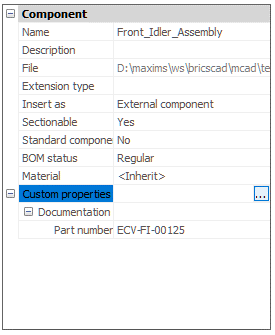
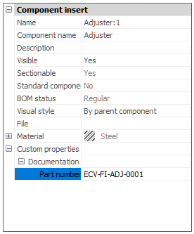
Do komponentów i wstawień komponentów można przypisywać niestandardowe właściwości. Podobnie jak właściwości niestandardowe BIM, właściwości niestandardowe komponentów są pogrupowane w zestawy właściwości, które odpowiadają grupom w przeglądarce mechanicznej lub panelu właściwości. Zestaw właściwości zawiera definicje właściwości, które określają nazwę i typ tej niestandardowej właściwości. Można również dodać predefiniowane wartości dla określonej właściwości niestandardowej.
Domyślnie zestawy właściwości mają zastosowanie do wszystkich elementów mechanicznych w dokumencie. Na przykład można zdefiniować zestaw właściwości z niestandardową właściwością "Numer części", a ta właściwość pojawi się dla każdej części w modelu. Jeśli komponent z tą właściwością zostanie wstawiony do innego dokumentu, właściwość ta pojawi się również dla wszystkich komponentów w tym dokumencie. Aby tego uniknąć, można użyć zestawów właściwości dla instancji. Te zestawy właściwości zostaną zastosowane tylko do określonych komponentów. Aby włączyć lub wyłączyć zestaw właściwości na instancję dla wybranych komponentów, użyj menu kontekstowego przeglądarki mechanicznej.
Wstawienia komponentów dziedziczą niestandardowe właściwości odpowiadających im komponentów. Możesz jednak dowolnie zmieniać dowolną właściwość niestandardową instancji; zmiany te zostaną zastosowane tylko do wybranych instancji komponentu i nie będą miały wpływu na inne instancje ani na sam komponent. Aby zmienić właściwości komponentu, należy otworzyć odpowiedni komponent i zmienić jego właściwości, wybierając węzeł główny w przeglądarce mechanicznej.
- Aby zmienić właściwości komponentu:
-
- Wybierz główny komponent w przeglądarce Mechanical .
- (opcjonalnie) W razie potrzeby skonfiguruj dostępne właściwości niestandardowe:
- Wywołanie polecenia BMWŁAŚCIWOŚCI ze wstążki lub wiersza poleceń
- lub wybierz właściwość Właściwości Niestandardowe i naciśnij przycisk Przeglądaj (
 ).
).
- (opcjonalnie) W razie potrzeby włącz zestawy właściwości instancji dla tego komponentu:
- Kliknij prawym przyciskiem myszy węzeł główny w przeglądarce, a następnie wybierz niezbędne zestawy właściwości w podmenu Właściwości niestandardowe.
- Wybierz wymaganą właściwość i wpisz lub wybierz nową wartość.
- Aby zmienić właściwości instancji najwyższego poziomu:
-
- Wybierz instancję komponentu w Przeglądarce Mechanicznej.

- (opcjonalnie) W razie potrzeby skonfiguruj dostępne właściwości niestandardowe:
- Wywołanie polecenia BMWŁAŚCIWOŚCI ze wstążki lub wiersza poleceń
- lub wybierz właściwość Właściwości niestandardowe i naciśnij przycisk Przeglądaj (
 ).
).
- (opcjonalnie) W razie potrzeby włącz zestawy właściwości instancji dla tego komponentu:
- Kliknij prawym przyciskiem myszy odpowiedni węzeł w przeglądarce, a następnie wybierz niezbędne zestawy właściwości w podmenu Właściwości niestandardowe.
- Wybierz wymaganą właściwość i wpisz lub wybierz nową wartość.
- Wybierz instancję komponentu w Przeglądarce Mechanicznej.

