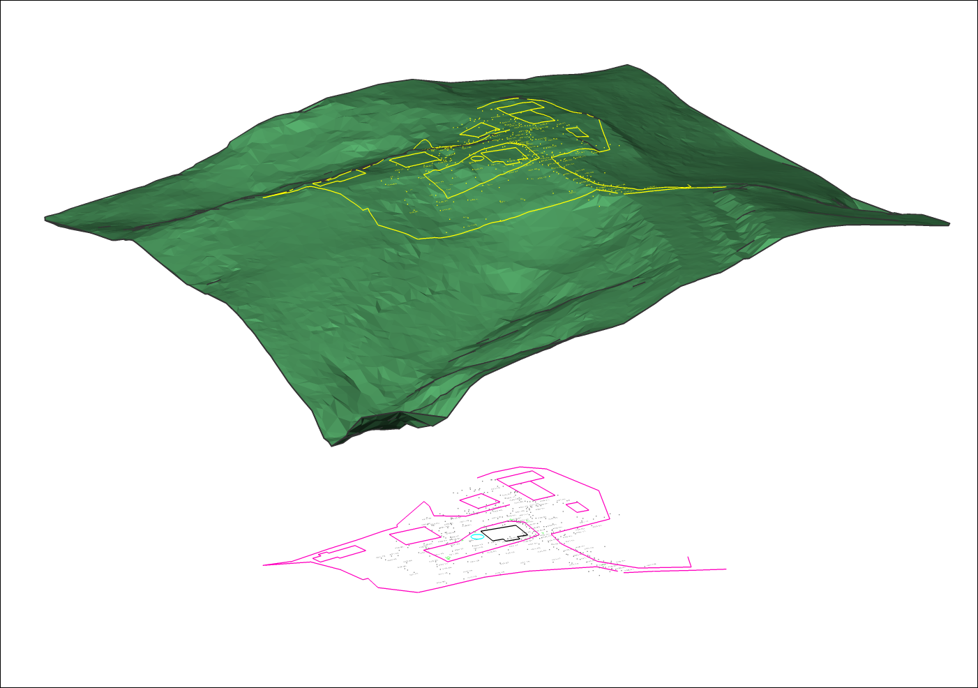
Tworzenie powierzchni TIN
Polecenia
TIN, TINPRZYPISZOBRAZ, TINPROJEKCJA
Przegląd
W BricsCAD® powierzchnia TIN (Triangulated Irregular Network) jest tworzona za pomocą polecenia TIN.
Powierzchnia TIN wykorzystuje dwa rodzaje danych wejściowych: punkty i linie nieciągłości (polilinie).
- Punkty zawierają współrzędne X, Y i wartości Z. Wszystkie punkty są używane do połączenia z dwoma najbliższymi sąsiadami w celu utworzenia trójkątów. Triangulacja powierzchni opiera się na algorytmie Delaunaya, który zapewnia, że żaden punkt nie znajduje się wewnątrz okręgu trójkąta.
- Linie nieciągłości reprezentują elementy infrastruktury liniowej, takie jak krawężniki, ściany oporowe itp. Linie te definiują również krawędzie trójkątów. Linie nieciągłości mogą być tworzone z elementów liniowych, takich jak linia, polilinia, łuk, okrąg.
- Granice to cechy definiujące ograniczone powierzchnie 3D. Granice powierzchni mogą być tworzone za pomocą zamkniętych polilinii. Zdefiniowanie zewnętrznych granic na dużej powierzchni 3D poprawia wydajność planu powierzchni TIN.
Tworzenie powierzchni TIN to proces, który należy wykonać, aby szczegółowo zmapować określony obszar. W modelach BIM powierzchnie te są wykorzystywane do reprezentowania terenu. Powierzchnia TIN może być generowana z dużych zbiorów danych, takich jak chmury punktów, z jednostek rysunkowych, z powierzchni 3D, z niestandardowych plików punktów ASCII, z powierzchni Civil 3D.
Ustawianie preferencji powierzchni TIN


- Aproksymacja łuku odległość środkowa
-
Uwaga: Odległość środkowa to maksymalna odległość między łukiem a segmentem cięciwy (prostej), która jest używana do aproksymacji łuku.
Określa, ile punktów wzdłuż krzywej ma zostać dodanych. W przypadku polilinii z krzywymi parametr ten umożliwia teselację łuków w polilinii. Domyślna wartość tego parametru jest zmienna w predefiniowanych szablonach BricsCAD. Na przykład wartość odległości jest ustawiona na 0,01 w szablonach BIM-m, 1 w szablonach BIM-cm, 10 w szablonach BIM-mm i 0,4 w szablonach imperialnych BIM.
- Włącz linie przerwania na przecięciach
-
Określa, czy dozwolone jest przekraczanie linii nieciągłości. Domyślnie jest ona ustawiona na Wł. Jeśli dozwolone jest przecinanie się linii nieciągłości, obliczane są przecięcia między segmentami linii nieciągłości i dodawane jako punkty do powierzchni TIN.
- Wzniesienie na przecięciach linii nieciągłości
- Określa, w jaki sposób powinna być określana wysokość na przecięciu linii nieciągłości. Istnieją trzy opcje (np. minimalna, maksymalna i średnia) definiowania wysokości linii nieciągłości na przecięciu.
- Asocjatywność
-
Włączanie/wyłączanie asocjatywności skarpy, powierzchni i korytarzy.
Domyślnie zmienna systemowa jest ustawiona na 15.
0: Nie jest włączona asocjatywność powierzchni TIN, skarpowania ani korytarza.
1: Włącza asocjatywność powierzchni TIN.
2: Włącza asocjatywność skarpowania.
3: Zarówno asocjatywność powierzchni TIN, jak i asocjatywność skarpowania są włączone.
4: Włącza asocjatywność powierzchni objętości TIN.
5: Asocjatywność powierzchni TIN i objętości TIN jest włączona.
6: Włączone są asocjatywności powierzchni skarpowania i objętości TIN.
7: Włączone są asocjatywności Powierzchni TIN, Skarpowanie i TIN powierzchnie objętościowe.
8: Włącza asocjatywność korytarza.
9: Włączona jest asocjatywność zarówno powierzchni TIN, jak i korytarza.
10: Włączone są asocjatywność skarpowania i korytarzy.
11: Skojarzenia powierzchni TIN, nachylenia i korytarza są włączone.
12: Włączona jest asocjatywność zarówno powierzchni objętościowej TIN, jak i korytarza.
13: Skojarzenia powierzchni TIN, powierzchni objętości TIN i korytarza są włączone.
14: Asocjatywność skarpowania, powierzchni objętości TIN i korytarza jest włączona.
15: Wszystkie asocjatywności powierzchni TIN, skarpowania, powierzchni objętości TIN i korytarza są włączone.
Właściwości powierzchni TIN
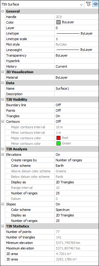
- Widoczność TIN
- Określa widoczność elementów powierzchni TIN.
- Linia graniczna
-
Zmienia widoczność zewnętrznej granicy na powierzchni TIN.
- Punkty
-
Zmienia widoczność punktów na powierzchni TIN.
- Trójkąty
-
Zmienia widoczność trójkątów na powierzchni TIN.
- Kontury
-
Określa widoczność konturów na powierzchni TIN.
- Interwał głównych konturów
-
Ustawia interwał głównych konturów.
- Mniejszy interwał konturów
-
Ustawia mniejszy interwał konturów.
- Kolor głównych konturów
-
Określa kolor głównego konturu.
- Kolor mniejszych konturów
-
Określa kolor mniejszego konturu.
- Analiza TIN
- Określa parametry wyświetlania analiz wysokości i nachylenia.
- Elewacje
- Jeśli opcja ta jest WŁĄCZONA, definiuje parametry wyświetlania analiz wysokości.
- Tworzenie zakresów przez
- Ustawia typ zakresu (Liczba zakresów, Przedział zakresu, Przedział zakresu z punktem odniesienia).
- Schemat kolorów
- Ustawia schemat kolorów dla analizy elewacji.
- Powyżej schematu kolorów odniesienia
- Ustawia powyższy schemat kolorów układu odniesienia.
- Poniżej schematu kolorów odniesienia
- Ustawia poniższy schemat kolorów układu odniesienia.
- Wyświetl jako
- Ustawia typ jednostek, które będą używane do wyświetlania analizy wysokości (trójkąty, kontury, punkty, trójkąty 2D, kontury 2D).
- Interwał zakresu
- Ustawia interwał zakresu.
- Liczba zakresów
- Ustawia liczbę zakresów.
- Podstawa
- Ustawia punkt odniesienia.
- Spadki
- Jeśli opcja ta jest WŁĄCZONA, definiuje parametry wyświetlania analiz nachyleń.
- Schemat kolorów
- Ustawia schemat kolorów dla analizy elewacji.
- Wyświetl jako
- Ustawia typ jednostek, które będą używane do wyświetlania analizy wysokości (trójkąty, kontury, punkty, trójkąty 2D, kontury 2D).
- Liczba zakresów
- Ustawia liczbę zakresów.
- Statystyki TIN
- Wyświetla statystyki TIN.
- Liczba punktów
-
Wyświetla liczbę punktów Powierzchni TIN.
- Liczba trójkątów
-
Wyświetla liczbę trójkątów powierzchni TIN.
- Minimalna wysokość
-
Wyświetla minimalną wartość wysokości znalezioną na powierzchni TIN.
- Maksymalna wysokość
-
Wyświetla maksymalną wartość wysokości znalezioną na powierzchni TIN.
- Obszar 2D
-
Wyświetla obszar 2D powierzchni TIN.
- Obszar 3D
-
Wyświetla obszar 3D powierzchni TIN.
Procedura: Tworzenie powierzchni TIN z elementów rysunku
- Otwórz rysunek zawierający jednostki rysunkowe, takie jak punkty CAD, bloki i polilinie.
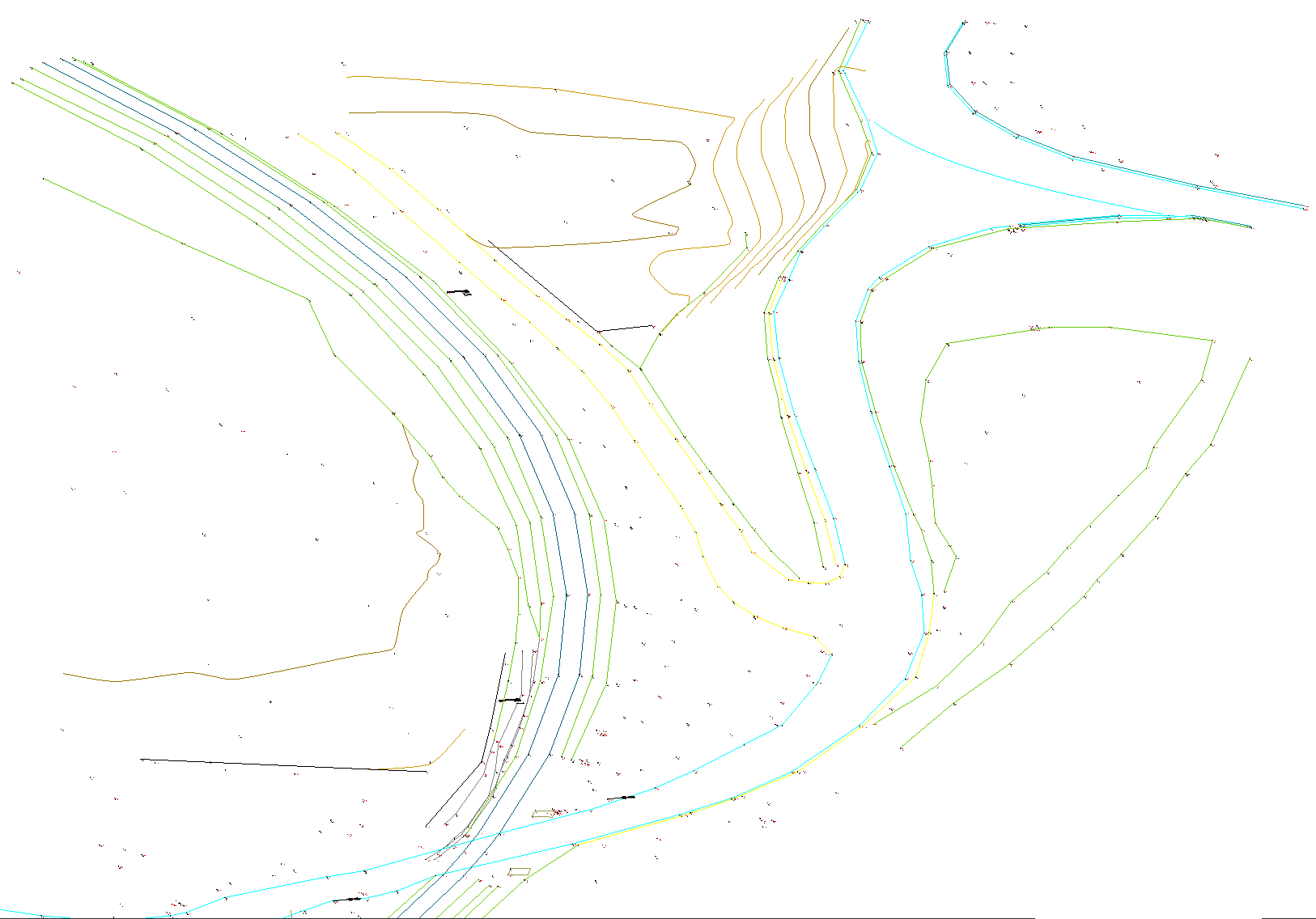
- Uruchom polecenie TIN.
- Zaznacz wszystkie jednostki na rysunku.
- Naciśnij ENTER
- Wybierz opcję w wierszu poleceń, aby zastosować wybrane elementy liniowe jako linie nieciągłości.
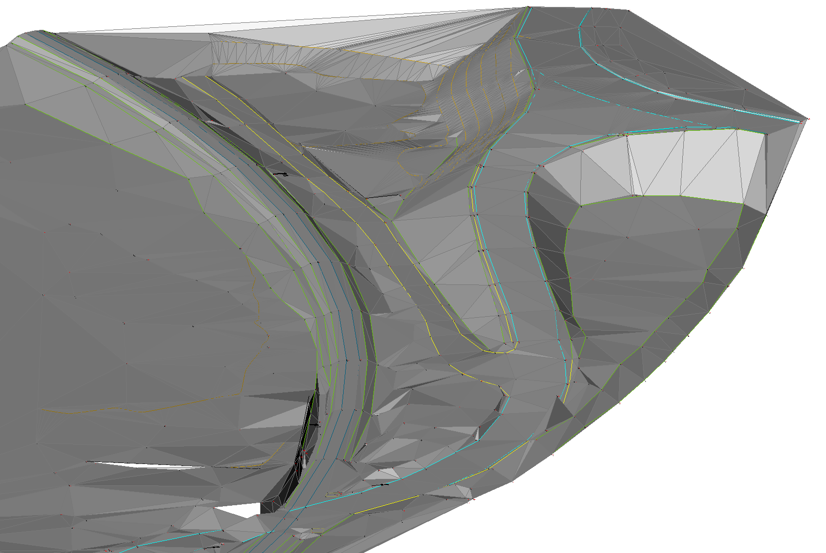
Procedura: Tworzenie powierzchni TIN z pliku punktów
- Uruchom polecenie TIN.
- Wybierz Importuj z pliku w wierszu poleceń.
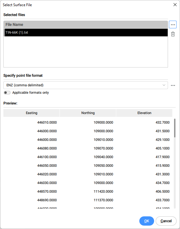
- W oknie dialogowym Wybierz Plik Powierzchni wybierz plik danych punktów, który chcesz otworzyć lub wybierz wiele plików do zaimportowania jednocześnie.
- Określ format pliku punktu z listy rozwijanej.Uwaga: Kliknij przycisk przeglądania w sekcji Określ format pliku punktów, aby zarządzać formatami plików powierzchni.
-
Przełącz Tylko obowiązujące formaty, aby automatycznie filtrować odpowiednie formaty plików punktów, zgodnie z wybranymi plikami punktów wejściowych.
-
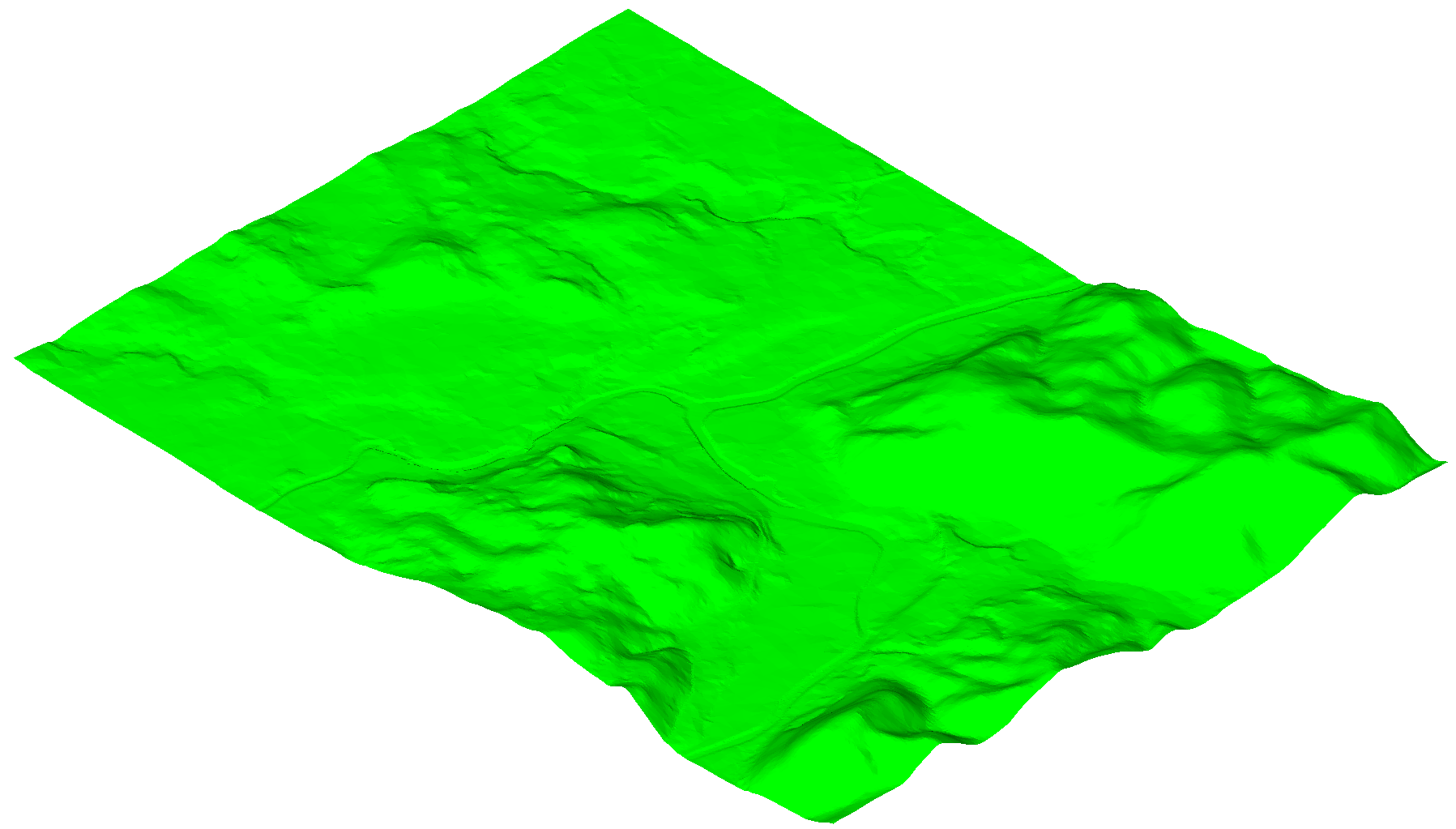
Kliknij OK, aby utworzyć powierzchnię TIN z pliku punktów.
- Wybierz Nie w wierszu poleceń, aby utworzyć powierzchnię TIN bez upraszczania punktów.Uwaga: Szczegółowe objaśnienia parametrów znajdują się w opisie algorytmu TIN Uprość.
Procedura: Tworzenie powierzchni TIN z pliku punktów przy użyciu Przytnij wielokątem
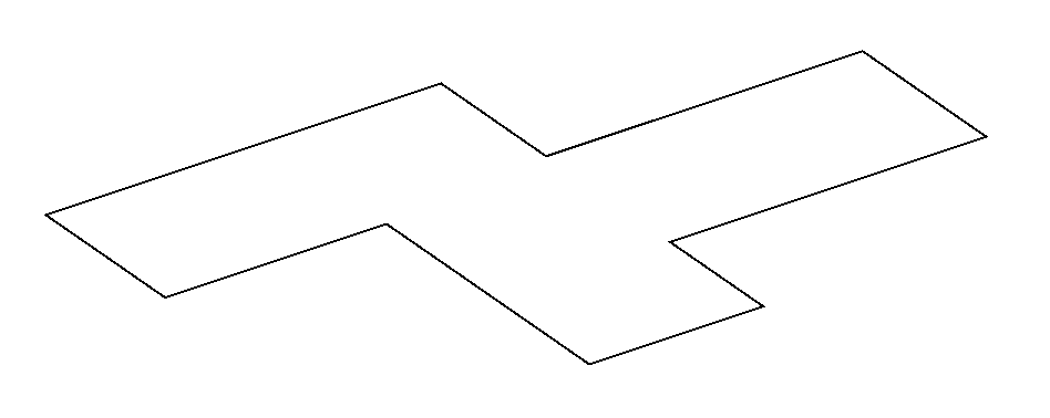
- Użyj istniejącej lub utwórz nową zamkniętą polilinię, aby utworzyć powierzchnię TIN wewnątrz tego obszaru.
- Uruchom polecenie TIN.
- Wybierz opcję Przytnij wielokątem w wierszu poleceń.
- Wybierz zamkniętą polilinię na rysunku, która ma zostać użyta jako wielokąt przycinający.
- Wybierz opcję Importuj z pliku w wierszu poleceń, aby utworzyć powierzchnię TIN z pliku punktów wewnątrz wybranego wielokąta przycinającego.Uwaga: Wybierz dowolną inną opcję: Wybrane elementy (rysunku), Utwórz z powierzchni, Utwórz z Chmury Punktów, Utwórz z Grup Punktów.
- Postępuj zgodnie z procedurą tworzenia powierzchni TIN z pliku punktów, która została opisana w tym artykule.
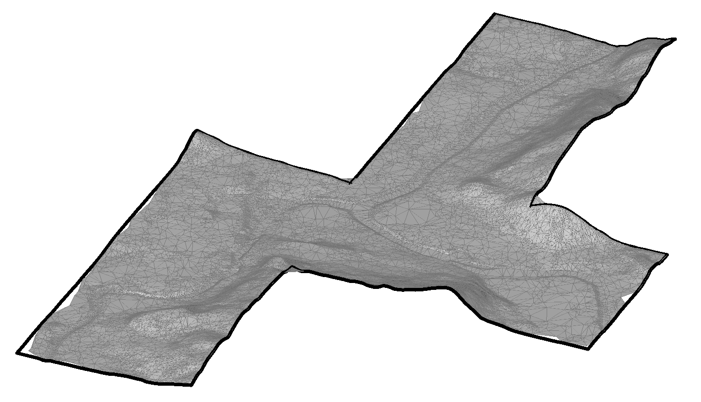
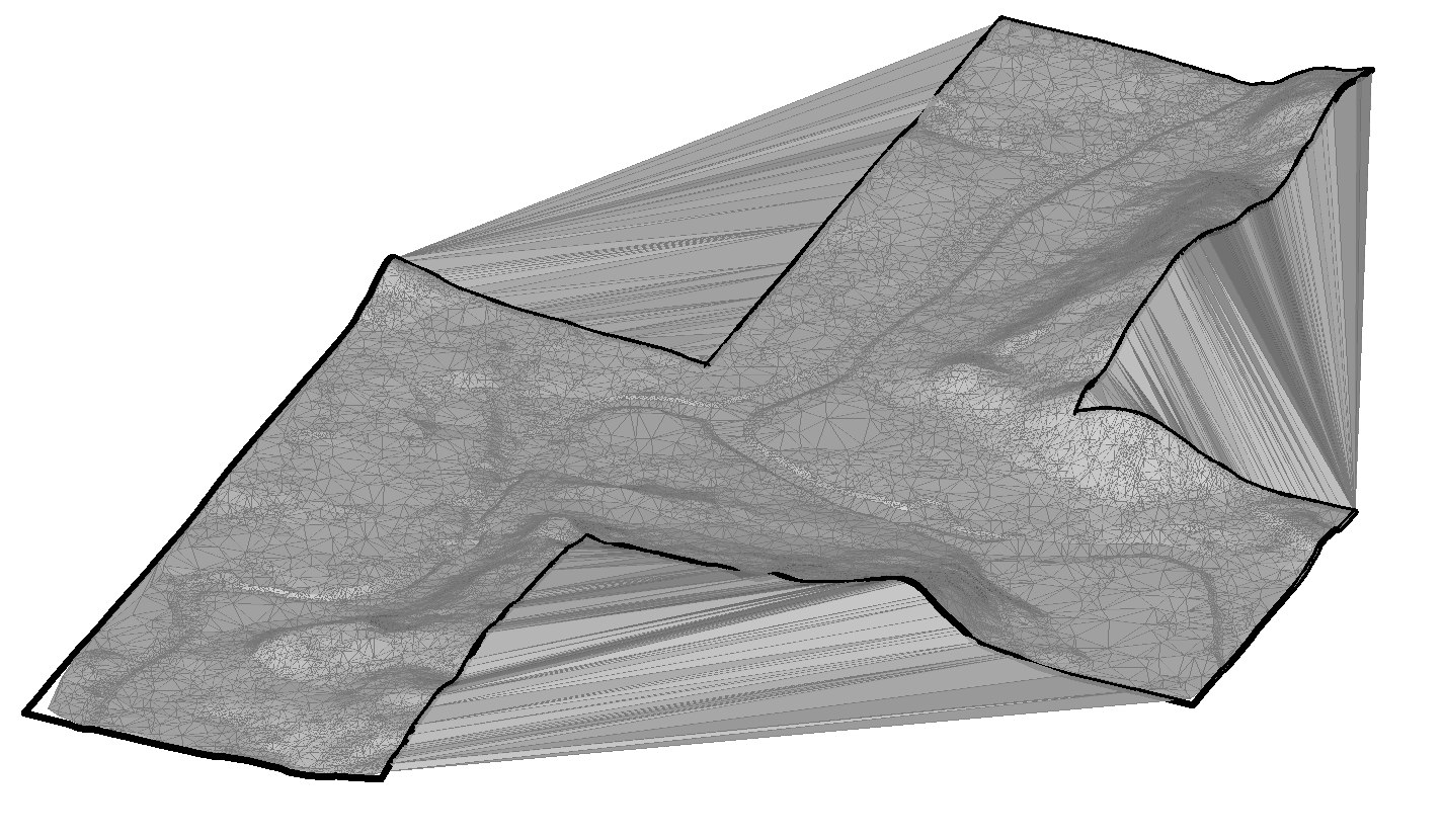 Uwaga: Algorytm powierzchni TIN łączy trójkąty poza granicą wklęsłego wielokąta przycinającego. W takich obszarach tworzone są długie i wąskie trójkąty, które można usunąć za pomocą polecenia TINEDYTUJ.
 - Uruchom polecenie TINEDYTUJ i wybierz opcję Usuń krawędzie zewnętrzne. Następnie określ maksymalną długość trójkąta. Trójkąty dłuższe niż określona wartość są usuwane.
Procedura: Tworzenie powierzchni TIN poprzez umieszczenie punktów
- Otwórz rysunek.
- Uruchom polecenie TIN.
- Wybierz opcję wstaw Punkty w wierszu poleceń.
- Wybierz punkt, w którym chcesz rozpocząć tworzenie powierzchni TIN.
Określ wartość wysokości każdego z tych punktów, a następnie naciśnij przycisk ENTER, aby zaakceptować.
Uwaga: Do utworzenia powierzchni TIN potrzebne są co najmniej trzy punkty.
Procedura: Tworzenie powierzchni TIN z powierzchni
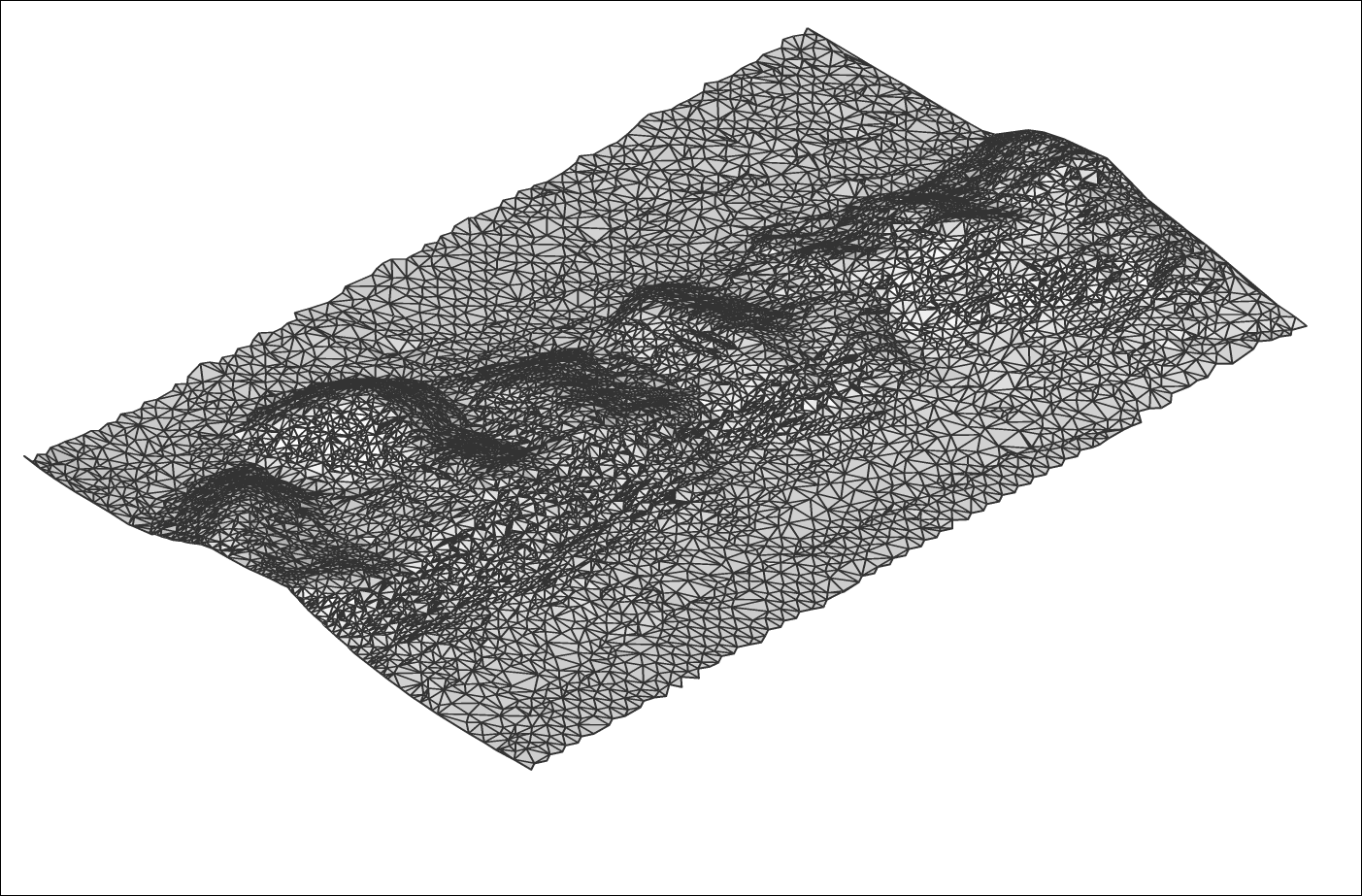
- Otwórz plik rysunku zawierający powierzchnie 3D.
- Uruchom polecenie TIN.
- Wybierz opcję Twórz z powierzchni w wierszu poleceń.
- Wybierz żądane powierzchnie 3D.
- Wybierz opcję, czy zastosować 3D Powierzchnie jako krawędzie (i widoczność), czy nie.Uwaga: Jeśli ta opcja jest zaznaczona, do utworzenia powierzchni TIN używane są krawędzie i wierzchołki powierzchni 3D. W przeciwnym razie do utworzenia powierzchni TIN używane są tylko wierzchołki powierzchni 3D. W rezultacie powierzchnia TIN nie podąża za krawędziami powierzchni 3D.
Procedura: Tworzenie powierzchni TIN z chmury punktów
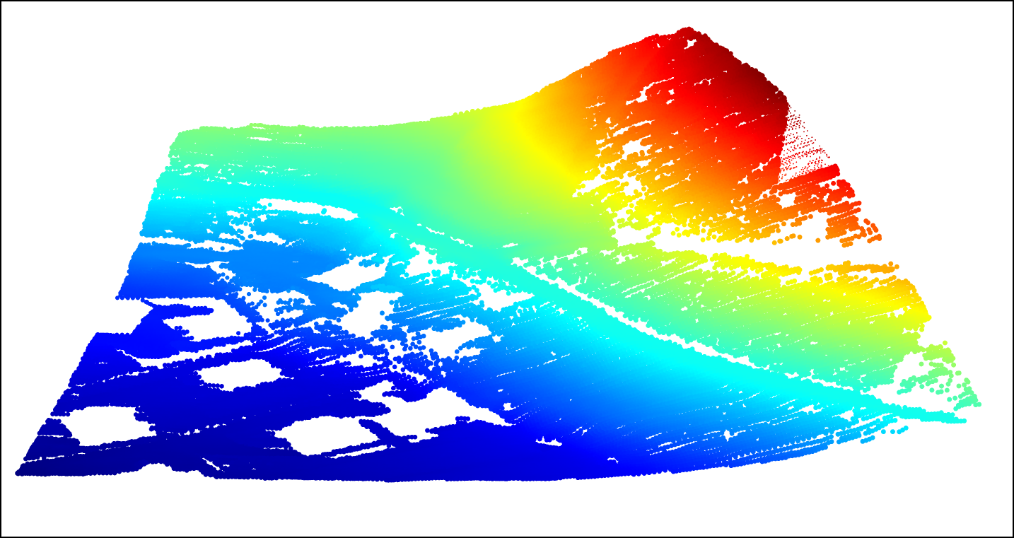
- Otwórz plik rysunku zawierający chmurę punktów.
- Uruchom polecenie TIN.
- Wybierz opcję Utwórz z Chmury Punktów w wierszu poleceń.
- Wybierz chmurę punktów na rysunku.
- Naciśnij przycisk ENTER.
- Wybierz Nie, aby utworzyć powierzchnię TIN bez użycia metody upraszczania.
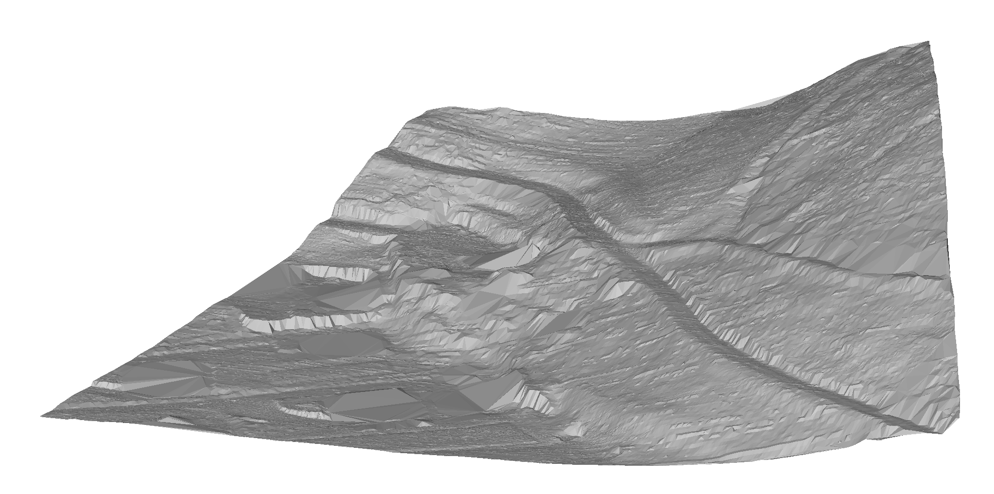
Obraz przedstawia oryginalną powierzchnię TIN utworzoną z chmury punktów zawierającej 87350 punktów.
Procedura: Użyj opcji TIN Uprość i TIN Zagęść podczas tworzenia powierzchni TIN z chmury punktów
W tej sekcji opisano procedurę tworzenia powierzchni TIN z chmury punktów, w której wykorzystano również opcje TIN Uprość i TIN Zagęść.
Wykonaj kroki od 1 do 5 procedury opisanej powyżej, aby utworzyć powierzchnię TIN z chmury punktów. Następnie wykonaj poniższą procedurę, aby skorzystać z opcji TIN Uprość i TIN Zagęść.
- Wybierz Tak, gdy wiersz poleceń oferuje opcję uproszczenia powierzchni TIN.
- Wprowadź promień dla kroku uproszczenia.
- Wprowadź różnicę wysokości.Uwaga: Szczegółowe objaśnienia parametrów znajdują się w opisie algorytmu TIN Uprość.
- Wybierz opcję Tworzenie powierzchni TIN w wierszu poleceń.
Możesz też wybrać opcję Uprość ponownie, aby edytować parametry uproszczenia.
Uwaga: Wiersz poleceń zgłasza liczbę punktów przed i po uproszczeniu, dzięki czemu użytkownik może podjąć lepszą decyzję dotyczącą kolejnych kroków.
- Wybierz Tak, aby zagęścić powierzchnię TIN.
Lub wybierz Nie, aby utworzyć uproszczoną powierzchnię TIN.
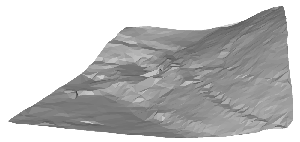
Obraz przedstawia uproszczoną powierzchnię TIN z 1562 punktami.
- Wprowadź różnicę wysokości.
- Wybierz jedną z opcji, aby określić obszar dla procesu TIN Zagęść: wybierz istniejące wielokąty na rysunku, narysuj nowy wielokąt lub naciśnij ENTER, aby użyć całej powierzchni TIN.Uwaga: Sprawdź opis algorytmu TIN Zagęść, aby uzyskać szczegółowe wyjaśnienie parametrów.
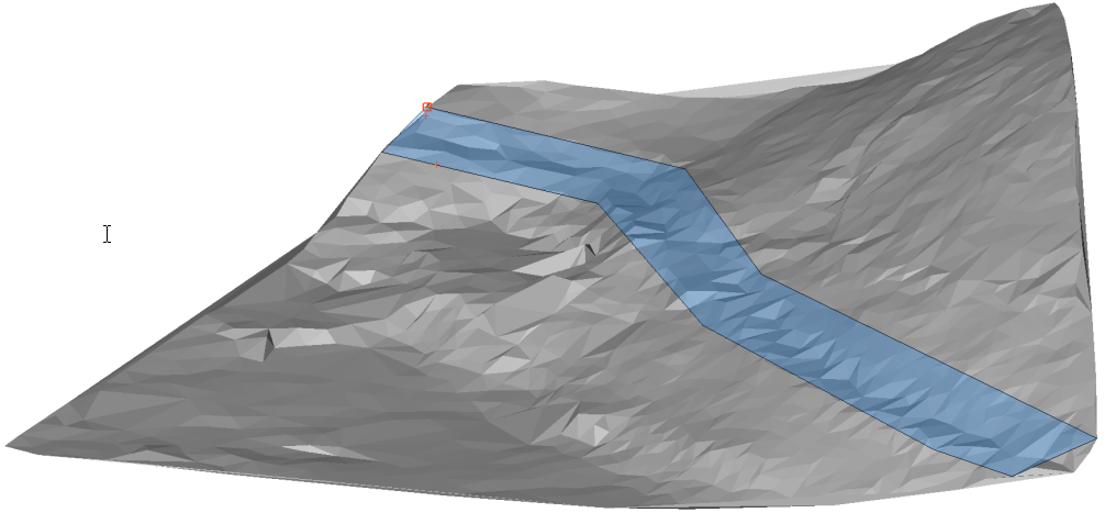
Obraz przedstawia wielokąt, który definiuje obszar zagęszczania TIN.
Uwaga: Końcowy wynik reprezentuje uproszczoną powierzchnię TIN, do której zwracane są poszczególne punkty w określonym wielokącie. Używając opcji TIN Zagęść na określonym obszarze na całej powierzchni TIN, osiągamy cel, aby w tym obszarze różnica wysokości między oryginalną a ostateczną powierzchnią TIN nigdy nie była większa niż określona wartość "różnicy wysokości" w kroku 6.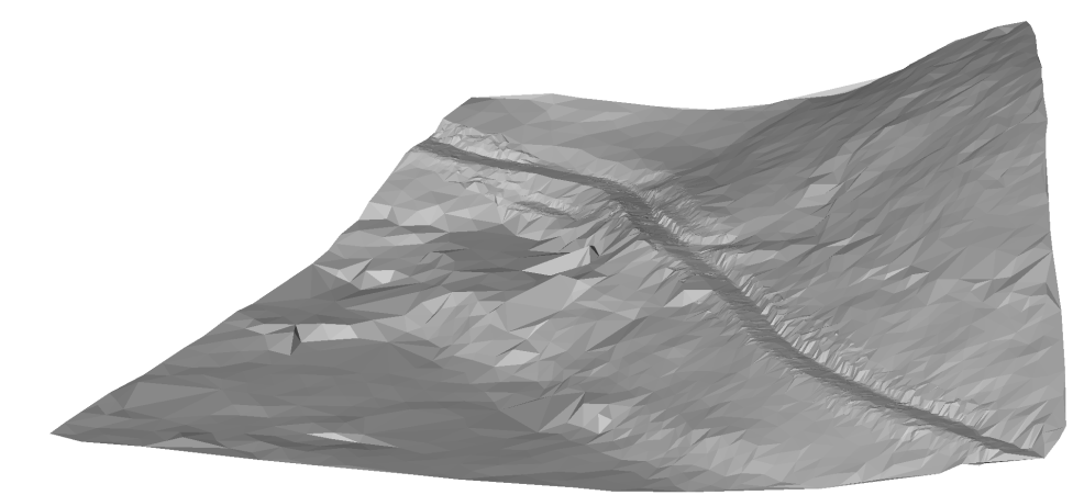
Obraz przedstawia ostateczną powierzchnię TIN z 6536 punktami. Oryginalna powierzchnia TIN składa się z 87350 punktów.
Uwaga: Parametry TIN Uprość i TIN Zagęść można edytować w dowolnym momencie w Eksploratorze Civil. Wybierz odpowiednią powierzchnię TIN, kliknij prawym przyciskiem myszy definicję Dodaj punkty i wybierz opcję Edytuj z menu kontekstowego. Otworzy się okno dialogowe Definicje Powierzchni, w którym można edytować wszystkie niezbędne parametry.
Procedura: Tworzenie powierzchni TIN z powierzchni Civil 3D
- Otwórz rysunek z powierzchnią Civil 3D.
- Uruchom polecenie CIVIL3DIMPORT.
- W oknie dialogowym Importuj Civil 3D wybierz Konwertuj z bieżącego rysunku.
-
Uwaga: Wybierz AutoCAD Civil 3D Powierzchnie, które zostaną przekonwertowane na BricsCAD Civil Powierzchnie TIN.Uwaga: W oknie dialogowym Importuj Civil 3D można również wybrać inne obiekty Civil 3D, takie jak grupy punktów, wyrównania i profile, które zostaną przekonwertowane na elementy BricsCAD Civil.
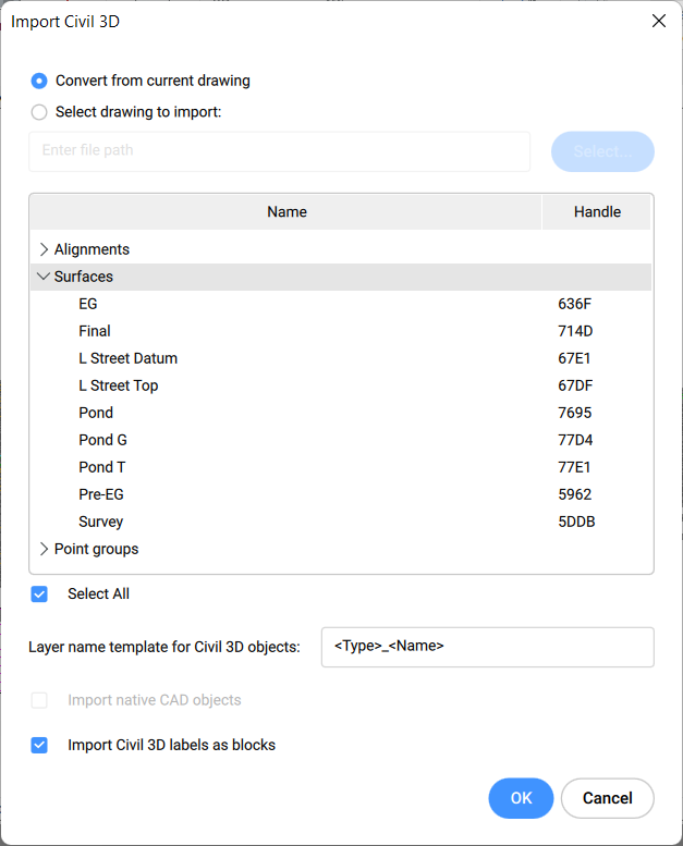
- Określa szablon nazwy dla obiektów Civil 3D.
- Zaznacz opcję Importuj etykiety Civil 3D jako bloki.
- Kliknij przycisk OK.
Informacje o TIN Przypisz Obraz
- Otwórz plik rysunku zawierający powierzchnię TIN i obraz.
- Uruchom polecenie TINPRZYPISZOBRAZ.
- Wybierz powierzchnię TIN.
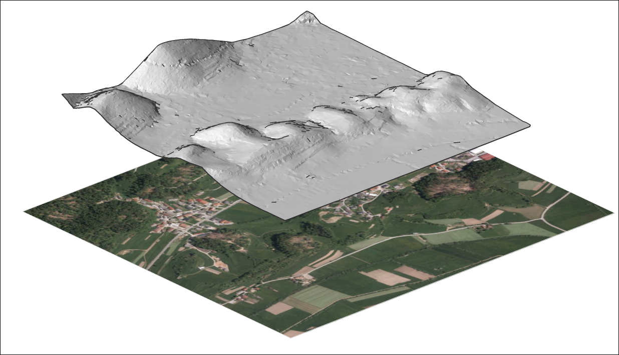
- Wybierz obraz rastrowy.
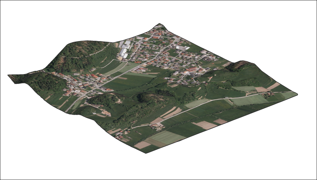 Uwaga: Jeśli obraz nie jest wyświetlany na powierzchni TIN, zmień Styl wizualny na Modelowanie lub Realistyczny i ustaw Trójkąty powierzchni TIN na WŁ.
O projekcie TIN
- Otwórz plik rysunku zawierający powierzchnię TIN i elementy (punkty, bloki, tekst, linie, polilinie, okręgi...).
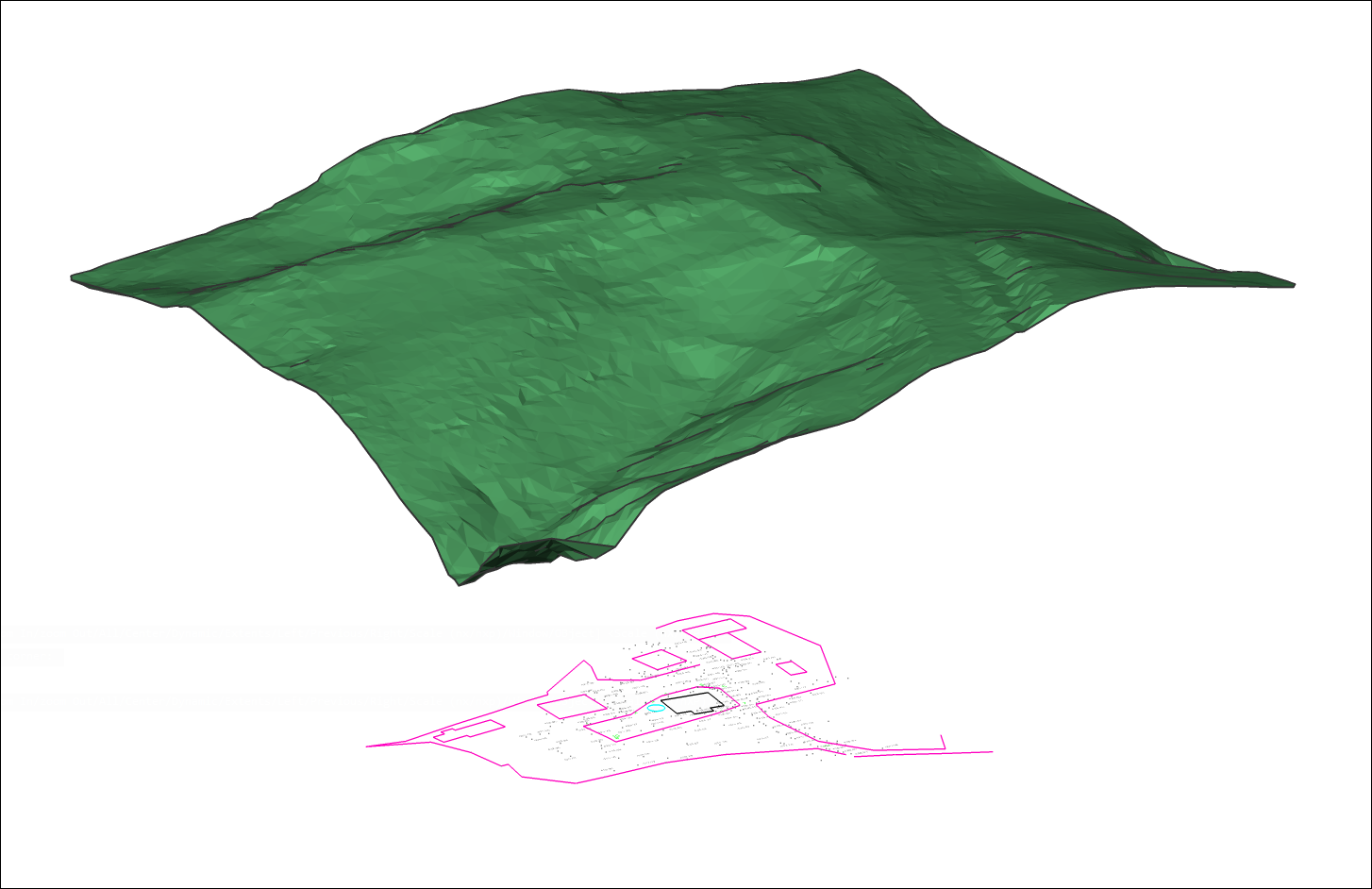
- Uruchom polecenie TINPROJEKCJA.
- Wybierz jednostki do projekcji.
- Wybierz, czy oryginalne jednostki mają zostać usunięte.
