BIMPRZEKRÓJ polecenie
Tworzy przekrój obiektu BIM.

Ikona: 
Opis
Tworzy jednostkę BIM z płaszczyzną przekroju (1) w płaszczyźnie XY bieżącego układu współrzędnych (GUW lub LUW) i kierunkiem widoku (2) w ujemnym kierunku Z bieżącego układu współrzędnych.
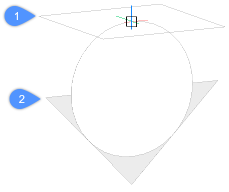
Uwaga: Jeśli dynamiczny LUW (UCSDETECT) jest włączony, płaszczyzna przekroju zostanie wyrównana do powierzchni bryły 3D pod kursorem.
Podmioty BIM Przekrój są tworzone na bieżącej warstwie. Oddzielna warstwa BIM_PRZEKRÓJ jest generowana w celu przechowywania wskaźników sekcji. Więcej informacji można znaleźć w artykule przewodnika Generowanie rysunków.
Metoda
Istnieje siedem typów jednostek BIM Przekrój, które można utworzyć za pomocą polecenia BIMPRZEKRÓJ:
- Rzut: wyświetla poziomą płaszczyznę przekroju przecinającą model.
- Przekrój: wyświetla pionową sekcję przecinającą model.
- Elewacja: wyświetla widok elewacji zewnętrznej modelu.
- Detale: wyświetla ręcznie zdefiniowaną objętość sekcji.
- Odwrócony rzut sufitu: wyświetla poziomą płaszczyznę przekroju przecinającą model, z kierunkiem widoku skierowanym w dół i liniami sufitu rzutowanymi na tę płaszczyznę.
- Elewacja wewnętrzna: wyświetla widok elewacji wewnętrznej dla każdej ściany wybranej przestrzeni.
- Wewnętrzne Plany Pięter: wyświetla poziomą płaszczyznę przekroju przecinającą wybraną przestrzeń, zawierającą powiązane wskaźniki elewacji wewnętrznych.
Uwaga: Właściwość Typ Przekroju wybranej jednostki BIM Przekrój można zmienić w panelu Właściwości.
Uwaga: Zmienna systemowa GENERATEASSOCVIEWS kontroluje, czy polecenie WIDOKPRZEKROJU tworzy rysunki 2D, które są trwale powiązane ze źródłowym modelem 3D. Jeśli GENERATEASSOCVIEWS jest włączone, wymiary asocjacyjne są aktualizowane automatycznie po zmodyfikowaniu modelu 3D i wykonaniu BIMAKTUALIZUJPRZEKRÓJ.
Opcje w ramach polecenia
- Wybierz punkt do umieszczenia przekroju
- Umożliwia określenie punktu.Uwaga: Płaszczyzna przekroju jest wyświetlana dynamicznie równolegle do płaszczyzny LUW XY poprzez pozycję kursora.
- Określ odległość
- Umożliwia wpisanie odległości lub określenie punktu.Uwaga: Zaleca się, aby Wymiary Dynamiczne (WYM) było aktywne. Umożliwia wprowadzenie odległości w dynamicznym polu wprowadzania.Uwaga: Płaszczyzna przekroju jest definiowana przez punkt lub w określonym odsunięciu od pierwszego punktu. Linia przekroju jest równoległa do osi X LUW lub dynamicznego LUW i przechodzi przez punkt w określonym przesunięciu od pierwszego punktu.Uwaga: Wyświetlana jest tylko linia przekroju i objaśnienia jednostki BIM Przekrój. Po podświetleniu lub wybraniu wyświetlana jest również płaszczyzna przekroju, granica przekroju i/lub objętość przekroju.
- Włącz obcinanie
- Ustawia właściwość Przytnij Widok na Wł.Uwaga: Ta opcja jest ustawiona domyślnie. Jeśli zmienna systemowa Asystent Skrótów Klawiszowych (HKA) jest włączona, naciśnij klawisz Ctrl, aby wyłączyć właściwość Przytnij Widok.Uwaga: Właściwość Przytnij Widok może być włączona jednocześnie w wielu przekrojach. Właściwość ta może zostać zapisana w widoku modelu (patrz polecenie WIDOK).
- Wyłącz obcinanie
- Ustawia właściwość Przytnij Widok na Wył.Uwaga: Właściwość Przytnij Widok można zmienić w panelu Właściwości.
- Detal
- Tworzy przekrój typu Detal. Więcej informacji można znaleźć w artykule przewodnika Definiowanie przekróju detalu.
- Wnętrze
- Tworzy elewacje wewnętrzne i plan pięter wybranych przestrzeni.Uwaga: Właściwość BIM/Elewacje Wewnętrzne przestrzeni jest ustawiona na Wł. Użyj polecenia BIMAKTUALIZUJPRZEKRÓJ, aby zaktualizować elewację wewnętrzną.
- Skala
- Ustawia właściwość Skala rzutni w pliku rysunku utworzonym przez polecenie BIMAKTUALIZUJPRZEKRÓJ. Uwaga: Domyślna Skala jest zapisywana za pomocą preferencji użytkownika SECTIONSCALE (domyślna wartość to 0,02) w oknie dialogowym Ustawienia.
- Odbity sufit
- Tworzy rzut sufitu na płaszczyznę przekroju.Uwaga: Odbity plan sufitu pokazuje rozmiar i lokalizację opraw oświetleniowych i innych struktur na suficie. Właściwość przycięcia widoku przekroju sufitu odbitego jest domyślnie Wył.
Edycja uchwytów
Obiekty BIM Przekrój mogą być edytowane za pomocą uchwytów, w zależności od ich właściwości Stan. Właściwość Stan można zmienić w panelu Właściwości.
- Stan Płaszczyzny:
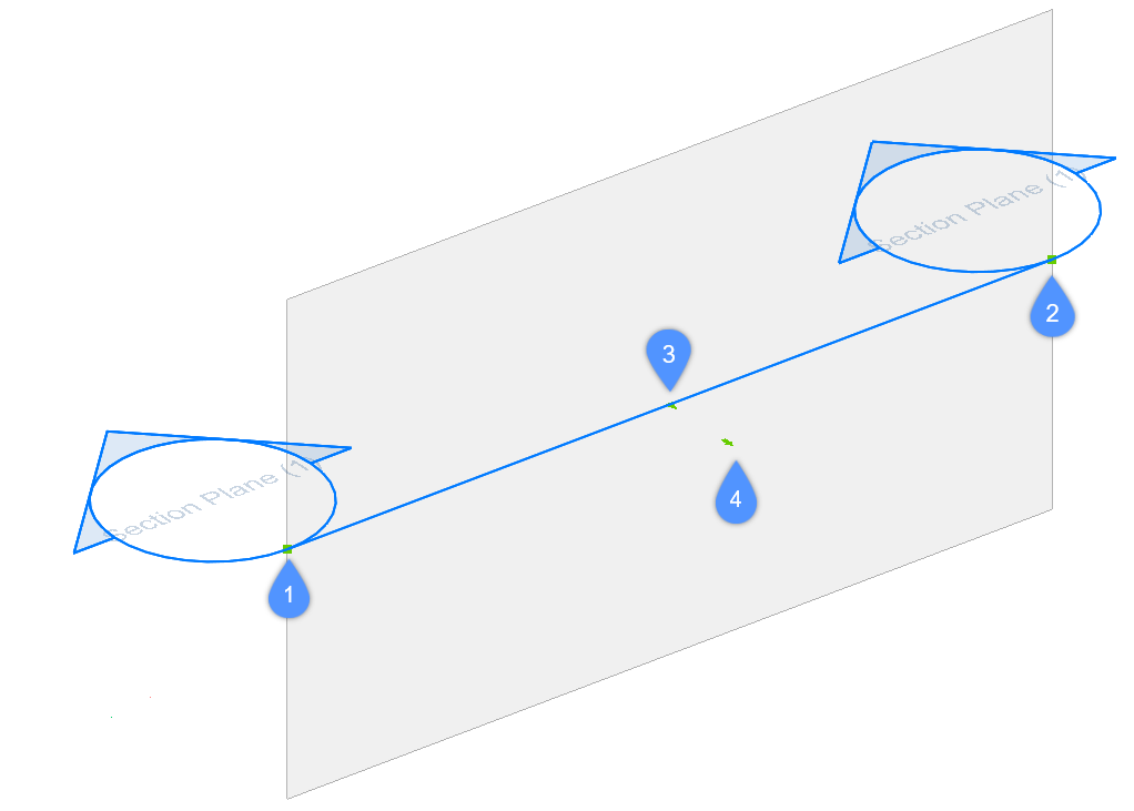
- Uchwyt Start (1) umożliwia przesuwanie przekroju i pozycji rozpoczęcia.
- Uchwyt końcowy (2) umożliwia modyfikację orientacji przekroju i położenia końcowego.
- Środkowy uchwyt (3) umożliwia przesuwanie przekroju i pozycji położenia środkowego.
- Strzałka (4) odwraca kierunek widoku.
- Stan Obwiedni:
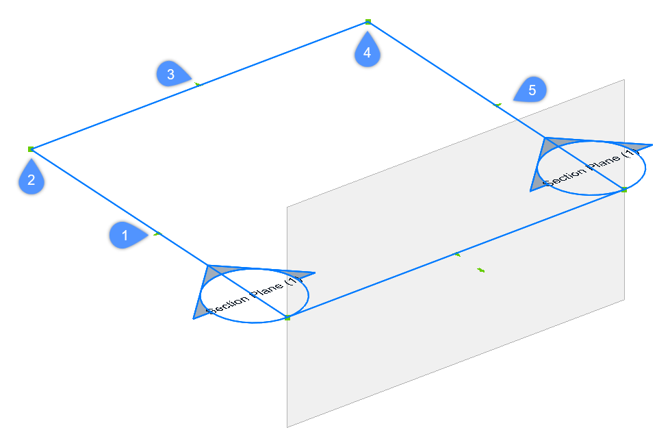
- Uchwyt punktu środkowego (1) umożliwia przesuwanie płaszczyzny przekroju.
- Uchwyt narożny (2 & 4) umożliwia deformację granicy przekroju/objętości.
- Uchwyt środkowy (3 & 5) umożliwia rozciągnięcie granicy przekroju/objętości.
- Stan Objętości:
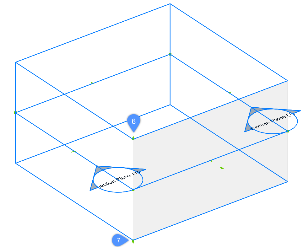
- (6) umożliwia przesunięcie górnej płaszczyzny przekroju.
- (7) umożliwia przesunięcie dolnej płaszczyzny przekroju.