


Selection dimensions
Selection dimensions provide an interface to easily reposition an existing BIM element (wall, column, window or door) by specifying the distances from the selected element to the reference points.
Selection dimension parts
To have access to selection dimensions, select an existing BIM element in the drawing by clicking it.
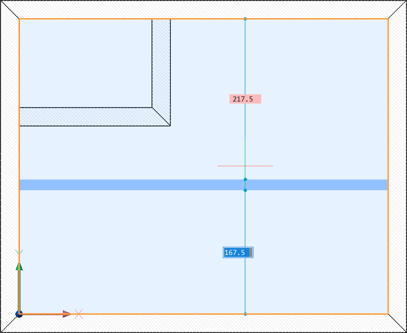
The four parts composing a selection dimension are:
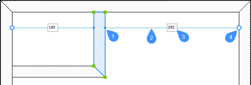
- Origin point
- Line
- Distance field
- Reference point
Using selection dimensions when moving entities
- (Optional) Enable Top View Mode (TVM) by clicking a story disk (
 ) in the Story Bar (see The Story Bar article).
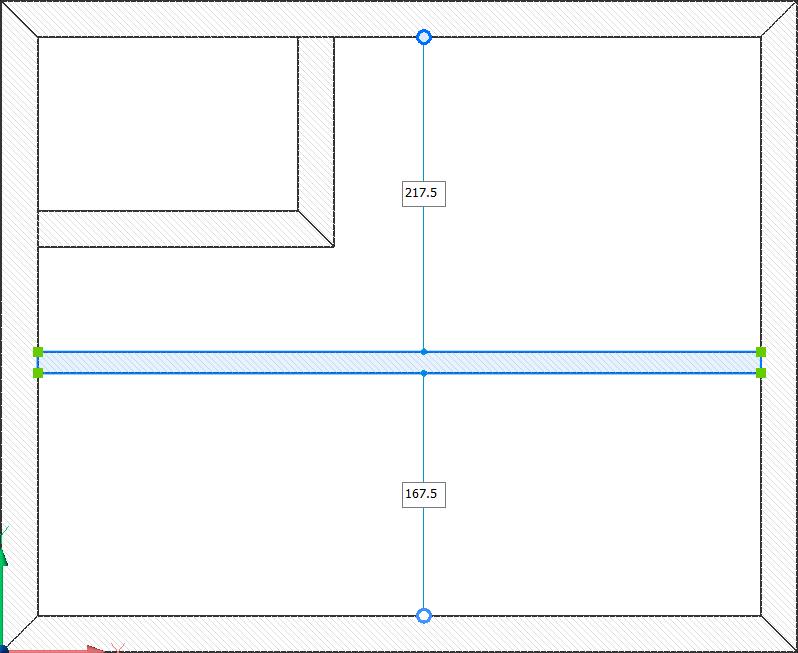
 - Select a BIM element in the drawing. The corresponding selection dimensions are displayed.
- (Optional) Choose a more convenient reference point with two clicks:
- Click a reference point to select it. The reference point becomes gray.
- Click a different point in the drawing to set it as the reference point. The distance fields update their value.
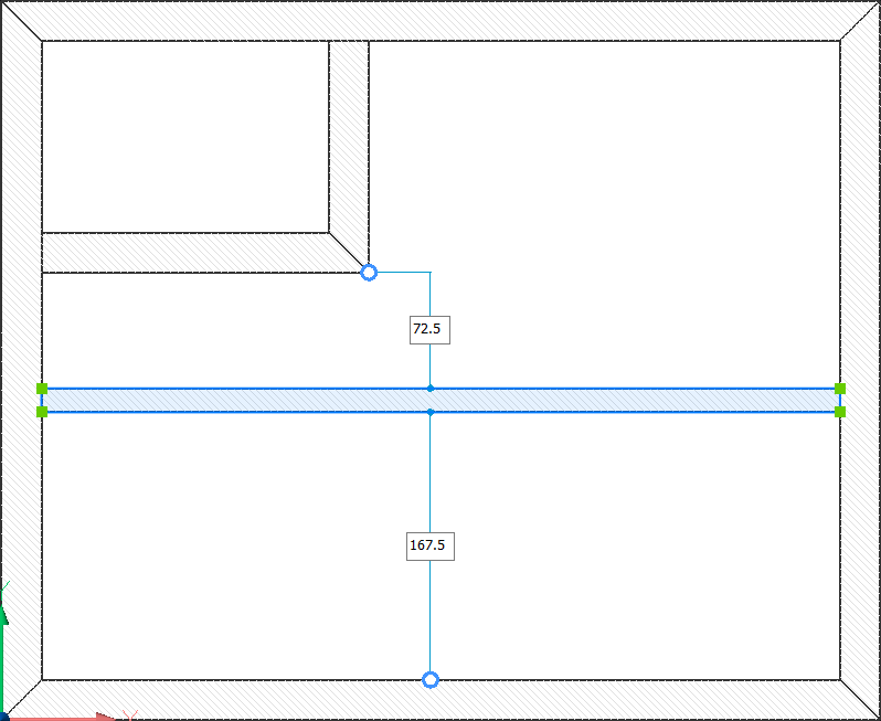
- Click a reference point to select it. The reference point becomes gray.
- Click a distance field.
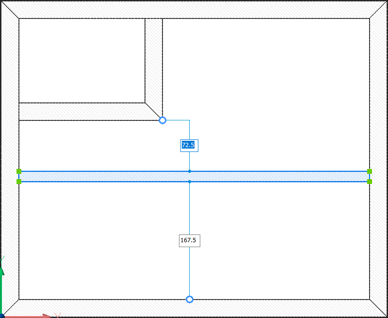
- (Optional) Press the Tab key to jump to the next distance field.
- Type in a value and press Enter. The BIM element is now repositioned accordingly.

- Press Esc to deselect the BIM element.
Note: The differences between dynamic and selection dimensions relate to when they are displayed and the possibility to manually move automatically detected points. These are listed in the table below:
| Dynamic dimensions | Selection dimensions |
|---|---|
|

|
|
|
See also Dynamic dimensions article.