


Comando ESTRUDI
Crea solidi o superfici 3D estrudendo entità.

Icona: 
Alias: EU
Descrizione
Crea solidi o superfici 3D estrudendo entità 2D aperte o chiuse, facce di solidi 3D, regioni o contorni chiusi.
Note:
- La variabile di sistema SELECTIONPREVIEW deve essere impostata su 2 o 3 per evidenziare le facce.
- A seconda del valore della variabile di sistema DELOBJ, le entità di origine vengono mantenute o eliminate. In caso contrario, viene richiesto se si desidera eliminare o meno le entità.
Metodo
Esistono due metodi per estrudere le entità:
- Creare solidi 3D.
- Creare superfici.
Opzioni all'interno del comando
- Modalità
- Permette di creare solidi o superfici.
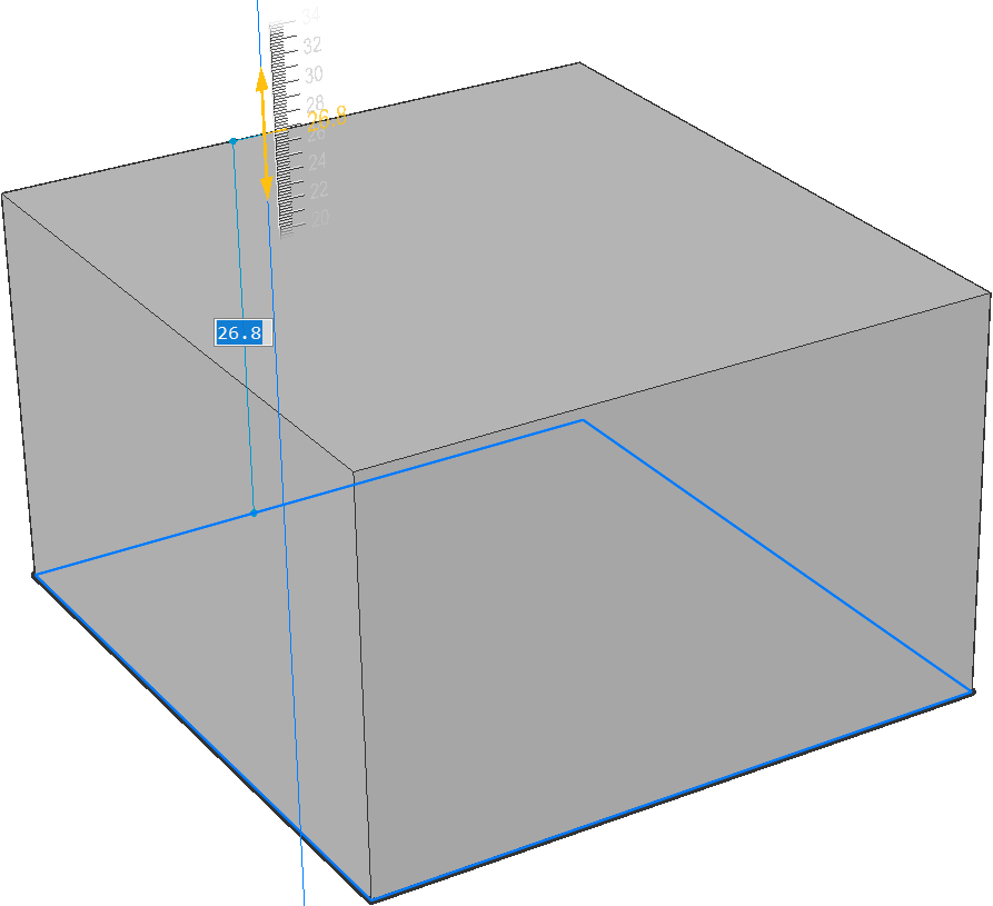
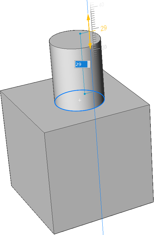
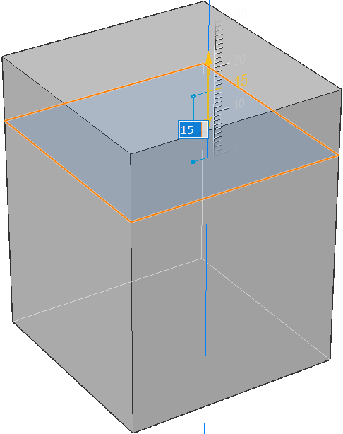
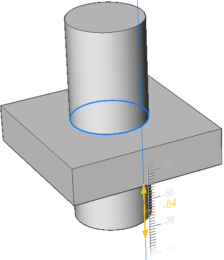
- Specificare l'altezza di estrusione
- Consente di impostare un'altezza di estrusione. L'altezza di estrusione viene misurata perpendicolarmente all'entità di origine.Note: È possibile specificare l'altezza in modo dinamico, utilizzando il Manipolatore, o digitando un valore di distanza.
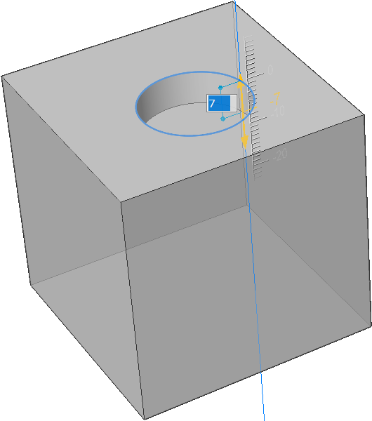
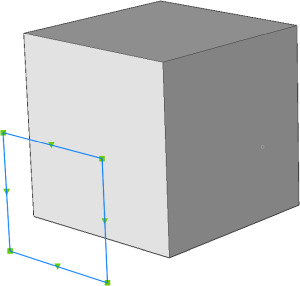
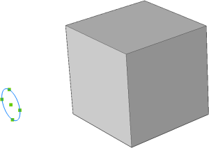
- Direzione
- Consente di specificare la direzione di estrusione.
- Percorso
- Specifica l'altezza di estrusione e la rastremazione in base a un'altra entità. Il programma utilizza la traiettoria per determinare come estrudere l'entità di origine.Note: L'entità traiettoria non può trovarsi sullo stesso piano dell'entità di estrusione.
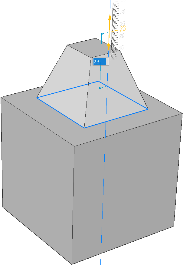
- angolo di Rastremazione
- Specifica l'angolo di rastremazione per l'estrusione. L'angolo viene misurato dalla direzione di estrusione. Un valore negativo si rastrema verso l'esterno.Note: L'angolo deve essere sufficientemente basso in modo che i lati inclinati non si intersechino dopo la parte superiore dell'estrusione.
- Auto
- Il risultato dipende dalla direzione di estrusione e dal valore delle quattro variabili di sistema Modalità estrudi: EXTRUDEOUTSIDE, EXTRUDEINSIDE, INTERSECTEDENTITIES e UNITESURFACES.
-
-
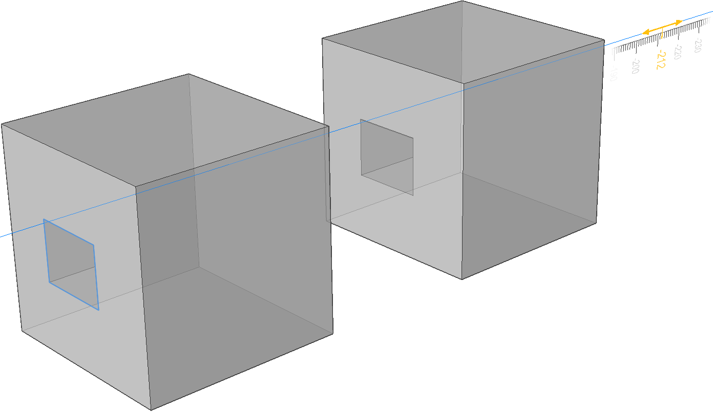
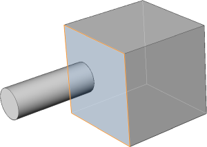
- Sottrai
- Il solido 3D viene sottratto da ciascun solido esistente interferente.
-
- Crea
- Viene creato un nuovo volume o una nuova superficie, indipendentemente dalla direzione di estrusione.
-
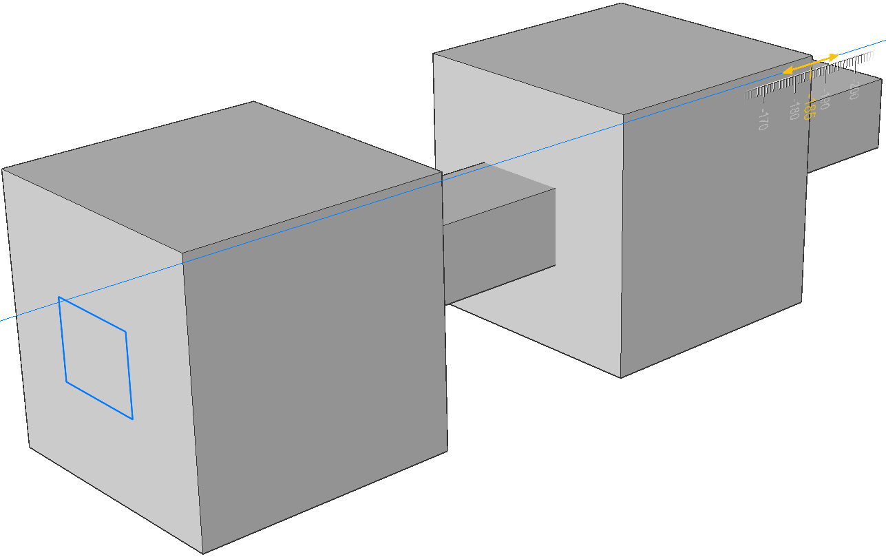
- Unisci
- Il nuovo solido 3D viene unito con ciascun solido esistente che interferisce.
-
- Trancia
- Taglia i solidi tramite la superficie estrusa.
-
-
- Entrambi i lati
- Estrude simmetricamente su entrambi i lati.
-
- ALlinea
- Consente di selezionare o definire un asse.
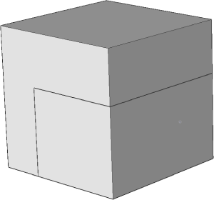
- imposta Limite
- Permette di limitare l'estrusione dalla faccia di un solido.
-
-
Note: Se la variabile di sistema HOTKEYASSISTANT è impostata su ON, viene visualizzato il widget Assistente Tasti di scelta rapida. Premere ripetutamente il tasto Ctrl durante la visualizzazione dinamica dell'estrusione per scorrere le varie opzioni