


Praca z chmurami punktów w BIM
O skanowaniu chmury punktów do przepływu pracy BIM
Półautomatyczny proces skanowania chmury punktów do BIM składa się z czterech kroków:
- 1. Wykrywanie pięter
- Użyj polecenia CHMURAPUNKTÓWWYKRYJPIĘTRA, aby wykryć podłogi. Do każdego wybranego punktu w chmurze punktów przypisywany jest numer piętra.
- 2. Wykrywanie przestrzenie
- Polecenie CHMURAPUNKTÓWWYKRYJPIĘTRA służy do wykrywania pomieszczeń. Do każdego wybranego punktu w chmurze punktów przypisywany jest numer pomieszczenia.
- 3. Tworzenie brył pomieszczenia
- Użyj polecenia CHMURAPUNKTÓWDOPASUJPRZESTRZENIE, aby utworzyć bryły pomieszczeń na podstawie wcześniej znalezionych pomieszczeń.
- 4. Tworzenie komponentów BIM
- Użyj polecenia BIMODWRÓĆPRZESTRZENIE, aby utworzyć ściany pomiędzy wybranymi bryłami, otworami ściennymi, ścianami zewnętrznymi i stropami.
Więcej informacji na temat przepływu pracy można znaleźć w artykule Skanowanie chmury punktów do przepływu pracy BIM.
Informacje o CHMURAPUNKTÓWDOPASUJPLANARNIE
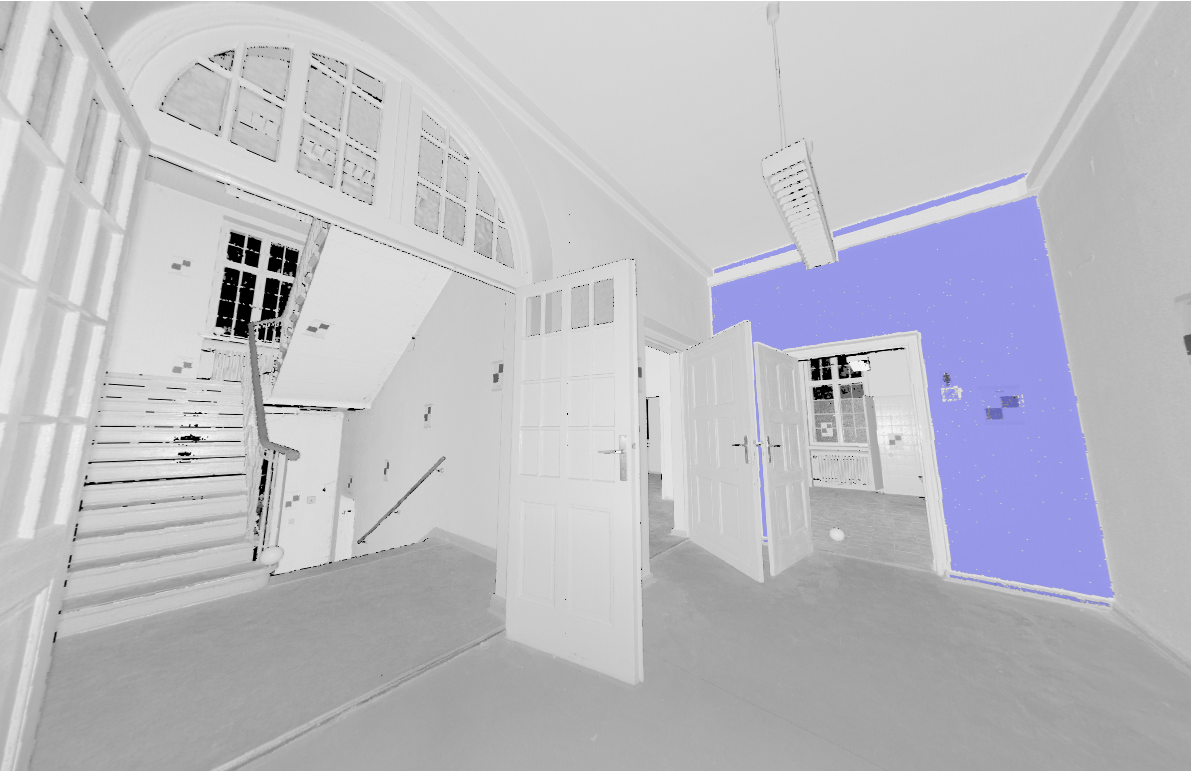
CHMURAPUNKTÓWDOPASUJPLANARNIE służy do półautomatycznego tworzenia geometrii 3D na podstawie skanu chmury punktów. Utworzy powierzchnię płaską lub bryłę po wybraniu punktu bazowego w chmurze punktów. Punkty, które wydają się znajdować na płaszczyźnie, nigdy nie znajdują się dokładnie na jednej płaszczyźnie, dlatego wartość progowa jest ustawiana jako właściwość jednostki chmury punktów. Działa to również w widoku bąbli.

Aby uzyskać więcej informacji na temat tego polecenia, zapoznaj się z artykułem Dokumentacja polecenia CHMURAPUNKTÓWDOPASUJPLANARNIE.
Tworzenie brył 3D z widoku bąbelków
- Kliknij dwukrotnie zielony dymek chmury punktów, aby otworzyć przeglądarkę dymków.
- Wpisz CHMURAPUNKTÓWDOPASUJPLANARNIE w wierszu polecenia.
- Wybierz żądaną ścianę.
- Naciśnij A, aby zaakceptować wybór.
(Opcjonalnie) Wybierz więcej ścian.
- Zamknij przeglądarkę dymków.
Powierzchnie zostaną utworzone i można je edytować w zamkniętych przestrzeniach za pomocą LPOŁĄCZ lub innych narzędzi łączących.
Tworzenie elementów 3D z obszaru modelu
Polecenia tego można również użyć w przestrzeni modelu, gdy przeglądarka Bubble Viewer nie jest otwarta. BricsCAD® poprosi o wybranie punktu chmury punktów w przestrzeni modelu. W zależności od rozmiaru przyciętej chmury punktów, trwa to dłużej, ale ma 2 zalety dzięki przeszukiwaniu wielu pozycji skanowania:
- Może tworzyć większe powierzchnie, na których widoczne są tylko części w każdej pozycji skanowania.
- Może wykrywać grubość ścian i płyt, ponieważ może uwzględniać przeciwległą powierzchnię.
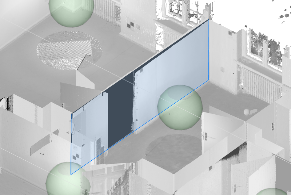
- Wpisz CHMURAPUNKTÓWDOPASUJPLANARNIE w wierszu polecenia.
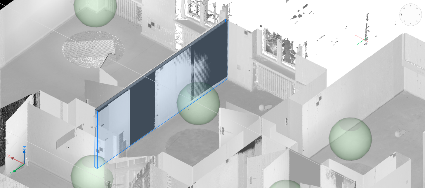
- Wybierz ścianę, na której chcesz utworzyć płaszczyznę lub bryłę.
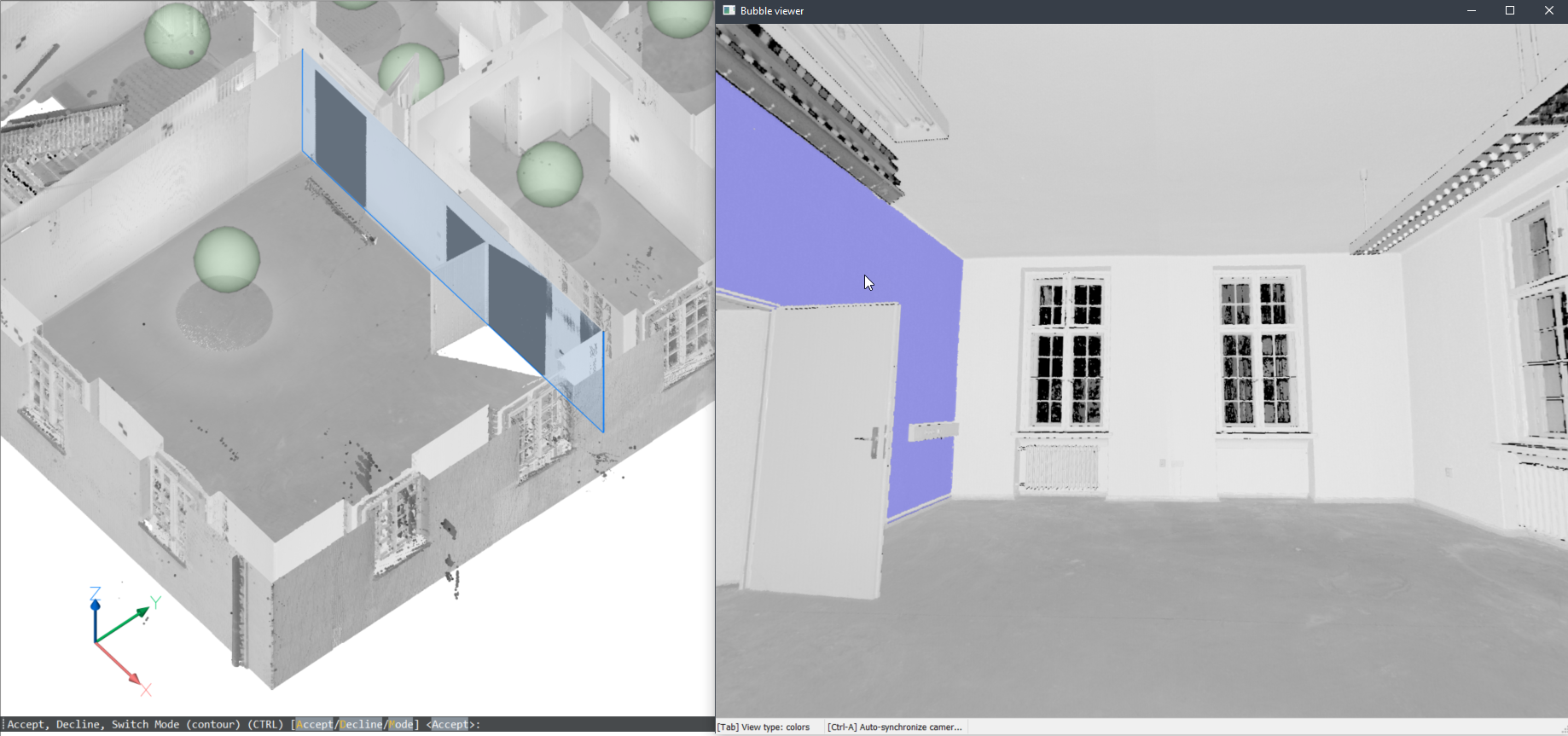
- Pojawi się monit: Akceptuj, Odrzuć, Przełącz tryb (kontur) (CTRL) [Akceptuj/Odrzuć/Tryb]:
- Naciśnij A, aby utworzyć ścianę.
- Naciśnij D, aby odrzucić.
- Naciskaj kilkakrotnie M lub CTRL, aby przełączać się między różnymi trybami.
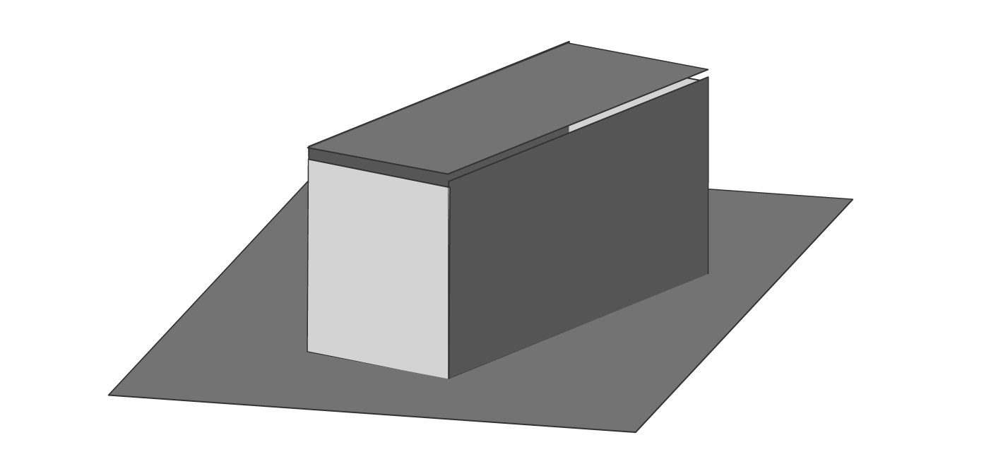
Tryb konturu utworzy najlepszą płaszczyznę dopasowania:

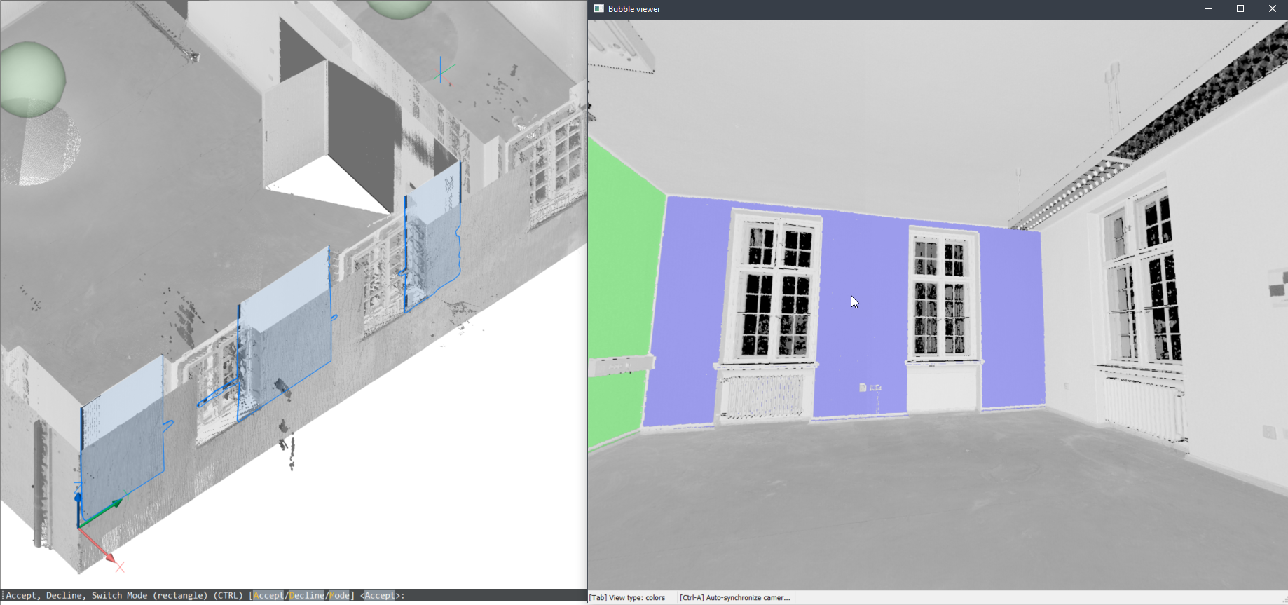
Tryb prostokątny utworzy prostokątną płaszczyznę wokół obszaru punktów płaskich:
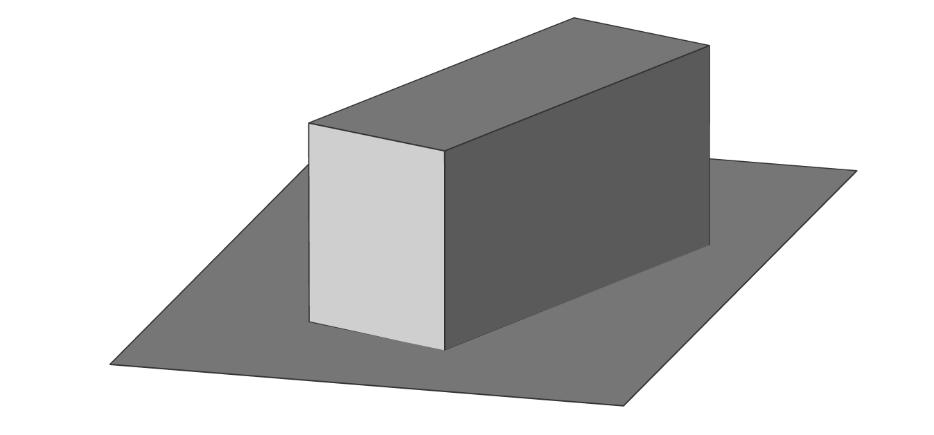
Tryb bryły utworzy bryłę z dwóch równoległych płaszczyzn chmury punktów:
Uwaga: Jeśli chmura punktów składa się z wielu pomieszczeń, można użyć trybu bryły, aby automatycznie utworzyć ściany bryłowe. - Naciśnij A, aby utworzyć ścianę.
Bryły te mogą być podstawą dla bardziej złożonego modelu BIM. Użyj poleceń modelowania, aby ukończyć budynek i dodaj dane BIM za pomocą Bimify, Automatch i Propagate , aby szybko przekształcić chmurę punktów w kompletny budynek BIM.
Pomocne może być włączenie ustawienia PUNKTY Najbliższy punkt chmury punktów (polecenie PCNAJBLIŻSZY zmienna systemowa 3DOSMODE). To ustawienie przyciągania znacznie poprawia możliwość wyboru odpowiednich punktów chmury punktów.
O sekcji CHMURAPUNKTÓWRZUTPRZEKROJU
Polecenie CHMURAPUNKTÓWRZUTPRZEKROJU automatycznie generuje obraz rastrowy z opcjonalnymi liniami konturowymi ze zdefiniowanego pola przekroju. Linie te można łatwo przekształcić w szczegółowy rysunek 2D.

Polecenie CHMURAPUNKTÓWRZUTPRZEKROJU umożliwia wykrywanie ścian z przekróju objętościowego chmury punktów w oparciu o różne opcje wykrywania ścian. Przekrój objętościowy można tworzyć za pomocą polecenia BIMPRZEKRÓJ. Przekrojów tych można użyć do wygenerowania linii 2D w celu utworzenia planu piętra 2D lub przekroju pionowego. Jest to proces działający w tle i wiele przekrojów może być przetwarzanych w kolejce. W ten sposób możliwe jest uruchomienie tego polecenia w pełnej rozdzielczości na wszystkich przekrojach.
W tym samym czasie generowany jest obraz rastrowy, aby dać użytkownikowi pewien kontekst. W niektórych przypadkach nie ma konieczności odtwarzania istniejącego budynku. Obrazy tła mogą nadać dokumentom projektowym o wiele więcej kontekstu. Można ich użyć do weryfikacji utworzonej geometrii 2D, ale w skanach o wysokiej jakości obrazy te mogą być również użyte jako materiał graficzny. Na przykład jako obraz tła dla modelu BIM w projektach renowacji, w których dokonuje się nowoczesnych interwencji w zabytkowych budynkach.
Aby uzyskać więcej informacji na temat tego polecenia, zapoznaj się z artykułem referencyjnym polecenia CHMURAPUNKTÓWRZUTPRZEKROJU.
Tworzenie obrazu rastrowego z chmury punktów
- Wpisz CHMURAPUNKTÓWRZUTPRZEKROJU w wierszu polecenia.
- Otworzy się panel Kontekst polecenia.
Edytuj opcje, aby dostosować wyświetlaną sekcję. Wyłącz opcję Wykryj ściany (1).
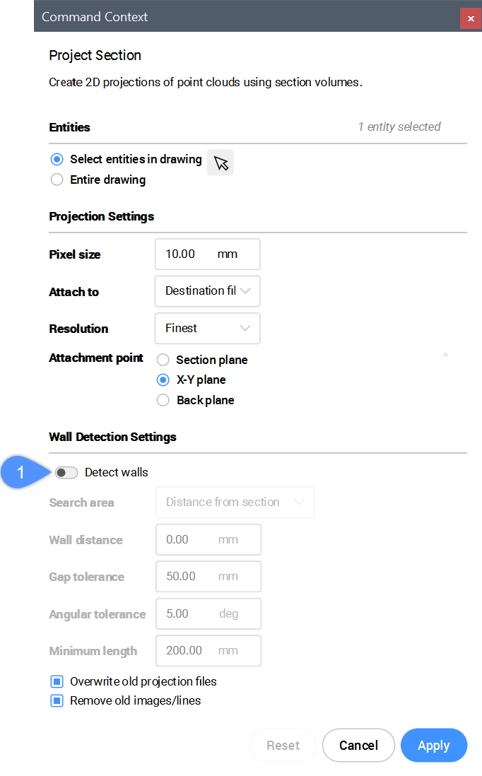
- Kliknij przycisk Zastosuj, aby wygenerować obraz rastrowy.
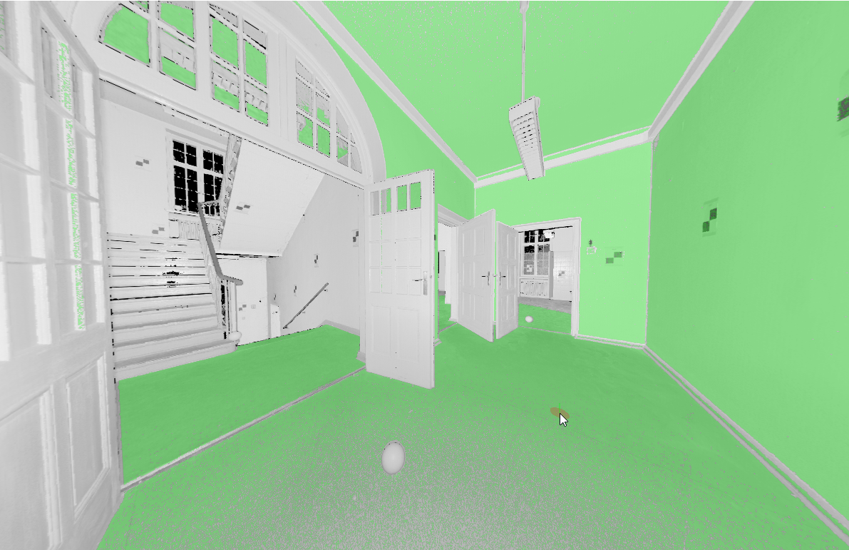
Skanowanie chmury punktów za pomocą realistycznych stylów wizualnych.
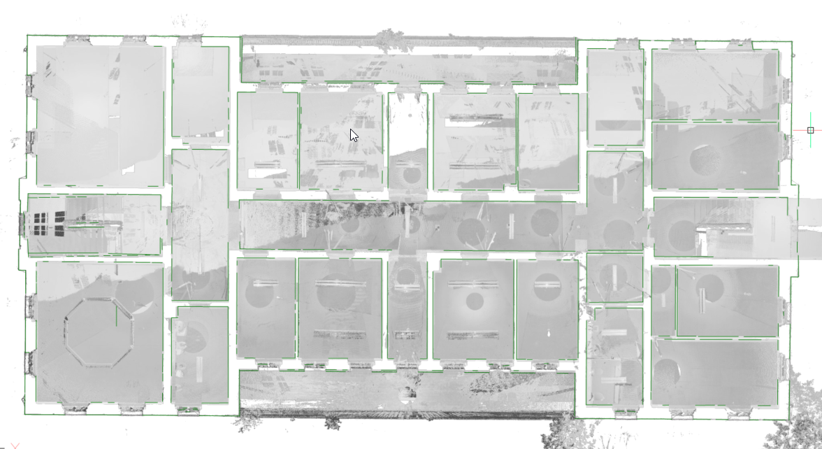
Wykrywanie ścian z chmury punktów i generowanie w 2D
Tworzenie przekrojów poziomych z chmur punktów
- Wpisz CHMURAPUNKTÓWRZUTPRZEKROJU w wierszu polecenia.
- Otworzy się panel Kontekst polecenia.
Edytuj opcje, aby dostosować wyświetlaną sekcję.
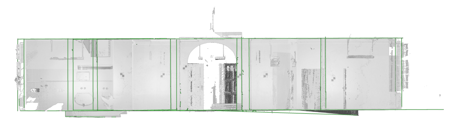
Uwaga: Włącz opcję Wykryj ściany (1), aby wygenerować zielone linie, jak pokazano na poniższym obrazku.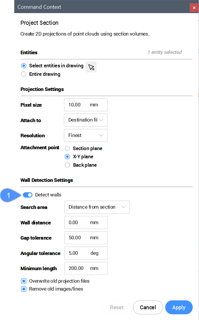
- Kliknij przycisk Zastosuj, aby wygenerować obraz rastrowy.Uwaga: Jeśli brakuje jakichś linii, możesz je narysować samodzielnie, śledząc obraz tła.
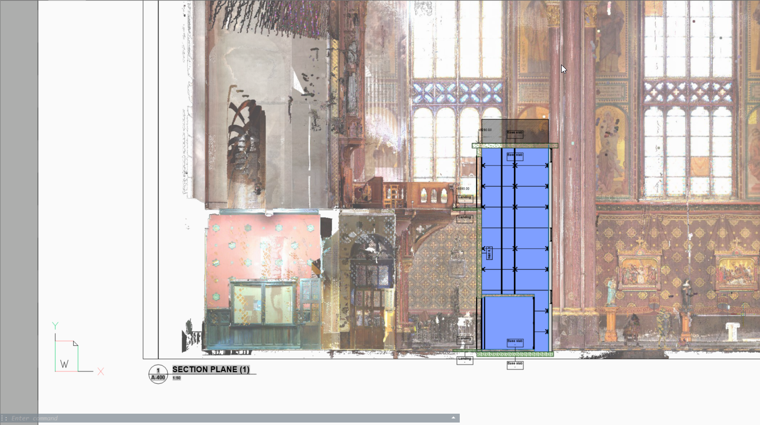
Tworzenie przekrojów pionowych z chmur punktów
Utwórz pole przekroju pionowego w miejscu, w którym chcesz wykonać rzut pionowy.
Upewnij się, że niebieska okrągła strzałka jest skierowana w stronę, w której chcesz wyświetlić projekcję.
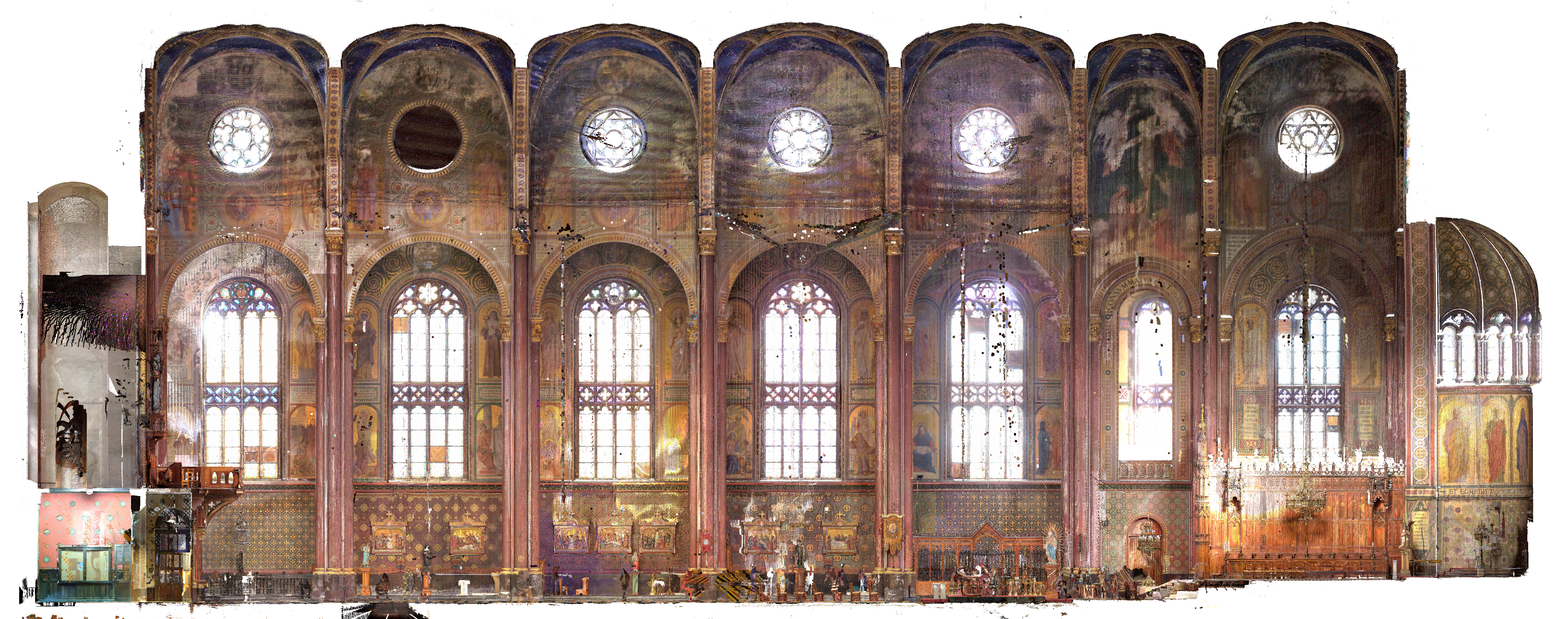
Generowanie przekrojów BIM z chmurami punktów
W niektórych przypadkach nie jest konieczne odtworzenie istniejącego budynku. Obrazy tła mogą zapewnić więcej kontekstu dokumentom projektowym. Obrazy te można wykorzystać do weryfikacji utworzonej geometrii 2D, a w wysokiej jakości skanach można je również wykorzystać jako materiał graficzny. Na przykład jako obraz tła dla modelu BIM w projektach renowacji, w których dokonuje się nowoczesnych interwencji w zabytkowych budynkach.
Skanowanie chmury punktów za pomocą realistycznych stylów wizualnych.