Working with Point Clouds in BIM
About point cloud scan to BIM workflow
The point cloud Scan to BIM semi-automatic workflow consists of four steps:
- 1. Detecting floors
- Use the POINTCLOUDDETECTFLOORS command to detect the floors. A floor number is assigned to each selected point in the point cloud.
- 2. Detecting rooms
- Use the POINTCLOUDDETECTROOMS command to detect rooms. A room number is assigned to each selected point in the point cloud.
- 3. Creating room solids
- Use the POINTCLOUDFITROOMS command to create room solids based on the previously found rooms.
- 4. Creating BIM components
- Use the BIMINVERTSPACES command to create walls in between the selected solids, wall openings, outer walls and slabs.
For more information about the workflow, see the Point cloud Scan to BIM workflow article.
About POINTCLOUDFITPLANAR
POINTCLOUDFITPLANAR is used to semi-automatically create 3D geometry based on a point cloud scan. It will create a planar surface or solid after selecting one point in a point cloud. The points that seem to be in a plane are never exactly in one plane, therefore a threshold value is set as a property of the point cloud entity. This also works in bubble view.

For more information about this command, visit the Command reference article POINTCLOUDFITPLANAR.
Creating 3D solids from the bubble view
- Double-click a green point cloud bubble to open the Bubble viewer.
- Type POINTCLOUDFITPLANAR in the Command line.
- Select the desired wall.
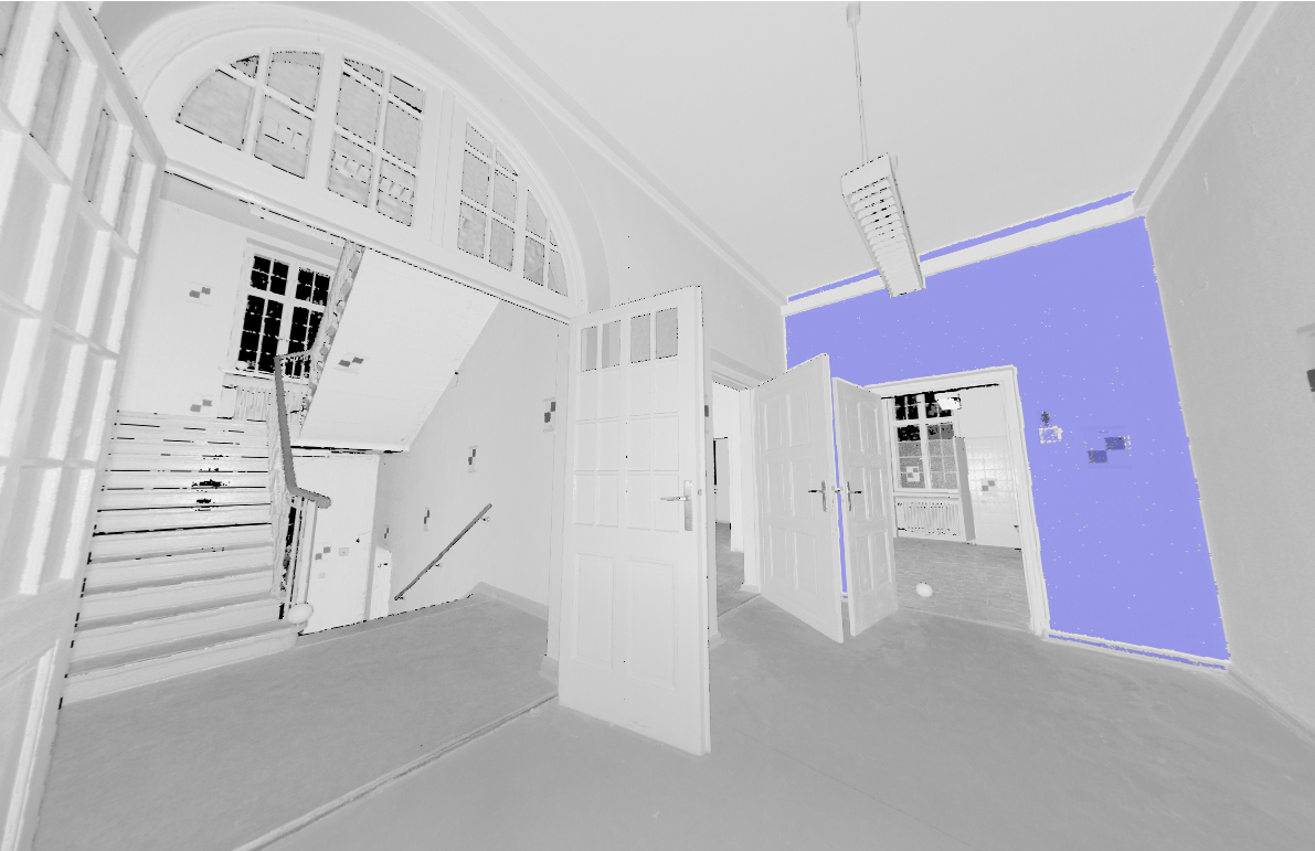
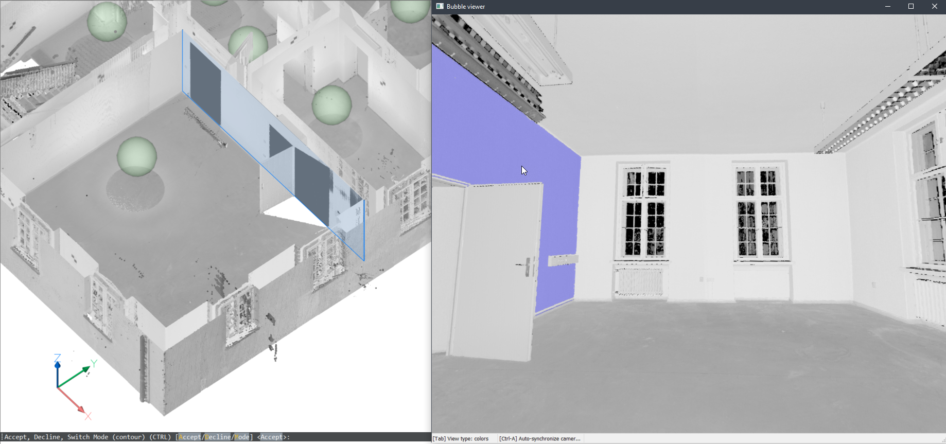
- Press A to accept the selection.
(Optional) Select more walls.
- Close the Bubble viewer.
The surfaces are created and you can edit them to closed spaces with LCONNECT or other connecting tools.
Creating 3D entities from the model space
You can also use this command in the model space when the Bubble viewer is not open. BricsCAD will ask you to select a point of the point cloud in model space. Depending on the size of the cropped point cloud, it takes longer but it has 2 advantages by searching multiple scan positions:
- It can create larger surfaces where only parts are visible in each scan position.
- It can detect wall and slab thickness since it can take the opposite surface into account.
- Type POINTCLOUDFITPLANAR in the Command line.
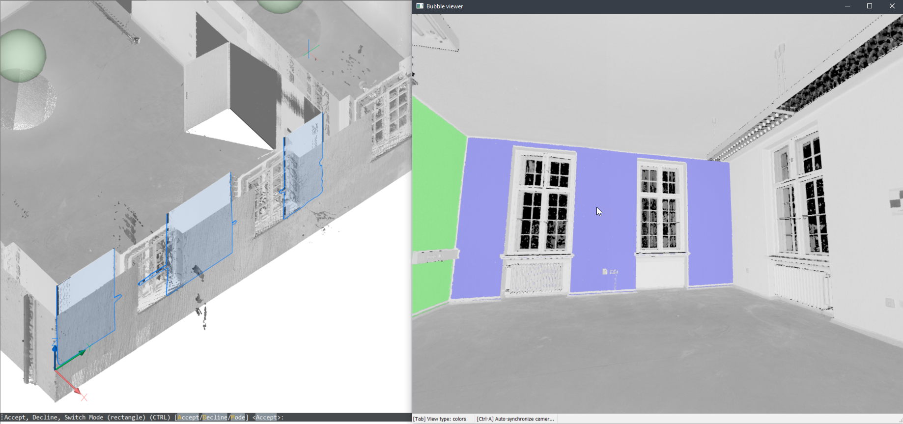
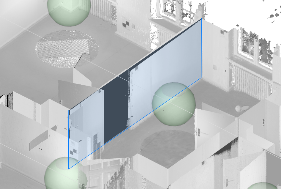
- Select a wall where you want to create a plane or solid.
- You are prompted: Accept, Decline, Switch Mode (contour) (CTRL) [Accept/Decline/Mode]:
- Press A to create the wall.
- Press D to decline.
- Press M or CTRL repeatedly to switch between different modes.
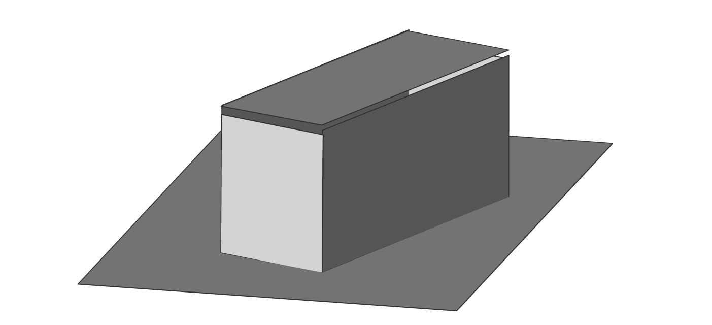
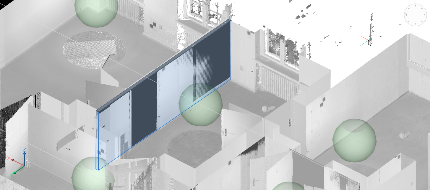
Contour mode will create the best fitting plane:

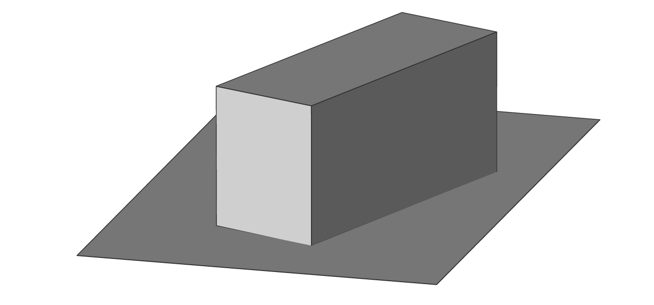
Rectangular mode will create a rectangular plane around region of planar points:
Solid mode will create a solid from two parallel point cloud planes:
Note: If the point cloud consists of multiple rooms, you can use the solid mode to automatically create solid walls. - Press A to create the wall.
These solids can be the base for a more complex BIM Model. Use modeling commands to complete the building and add BIM data with Bimify, Automatch and Propagate to quickly transform your point cloud into a complete BIM Building.
It may be helpful to turn on the Pointcloud Nearest Point ESNAPsetting (PCNEAREST command/3DOSMODE system variable). This snap setting significantly improves your ability to select relevant point cloud points.
About POINTCLOUDPROJECTSECTION
The POINTCLOUDPROJECTSECTION command automatically generates a raster image with optional contour lines out of a defined section box. These lines can be easily manipulated into a detailed 2D drawing.

The POINTCLOUDPROJECTSECTION command enables you to detect walls from the volume section of a point cloud based on a variety of wall detection options. You can create volume sections with the BIMSECTION command. You can use these sections to generate 2D lines to create a 2D floor-plan or a vertical section. This is a background process and multiple sections can be processed in a queue. This way, it is possible to run this command in full resolution on all sections.
At the same time, a raster image is generated to give the user some context. In some cases, it is not necessary to recreate the existing building. Background images can give much more context to the design documents. These can be used to verify the created 2D geometry but in high quality scans, these images can also be used as graphical material. For example, as a background image for a BIM model in renovation projects where modern intervention are made in historical buildings.
For more information about this command, visit the Command reference article POINTCLOUDPROJECTSECTION.
Creating a raster image from a point cloud
- Type POINTCLOUDPROJECTSECTION in the Command line.
- The Command Context panel opens.
Edit the options to customize your projected section. Turn the Detect walls (1) option off.
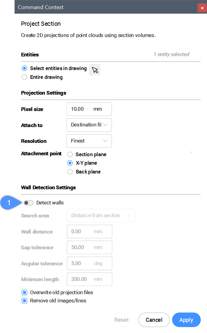
- Click Apply to generate the raster image.
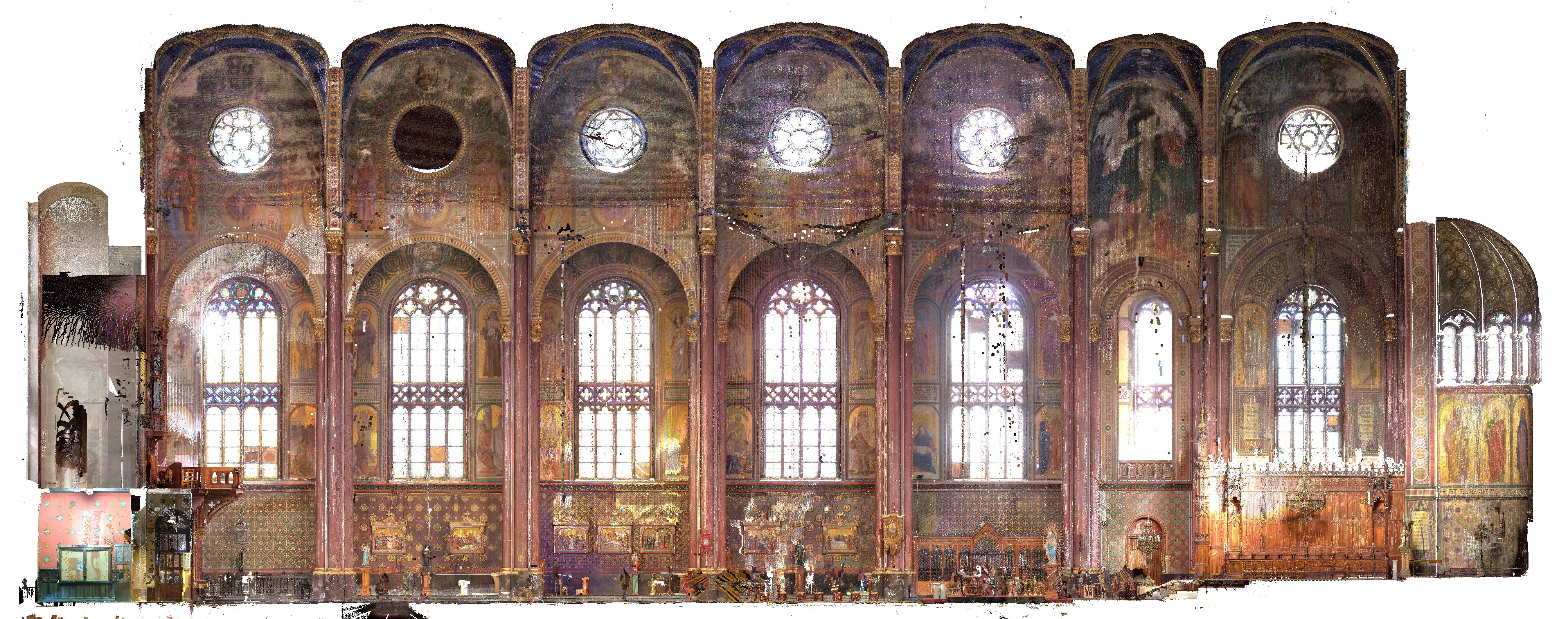
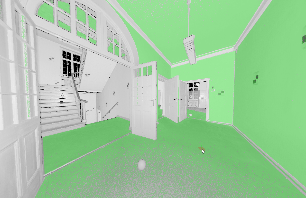
Point Cloud scan by Realistic Visual styles.
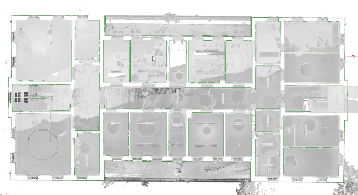
Detecting walls from a point cloud and generate in 2D
Making horizontal sections from point clouds
- Type POINTCLOUDPROJECTSECTION in the Command line.
- The Command Context panel opens.
Edit the options to customize your projected section.
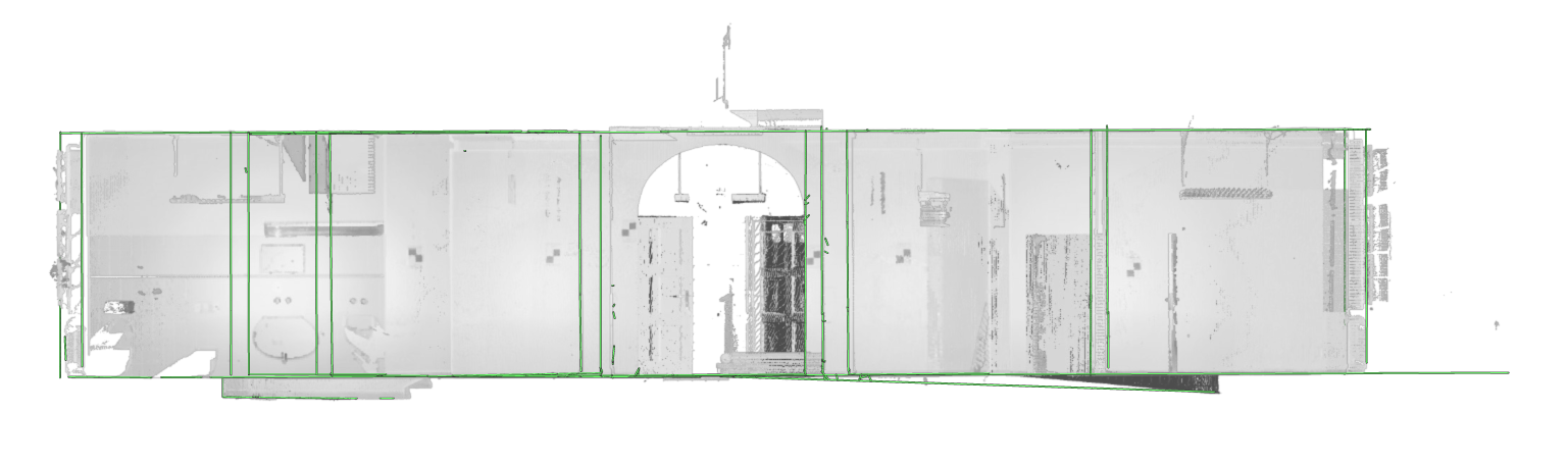
Note: Turn on the Detect walls option (1) to generate the green lines as seen in the image below.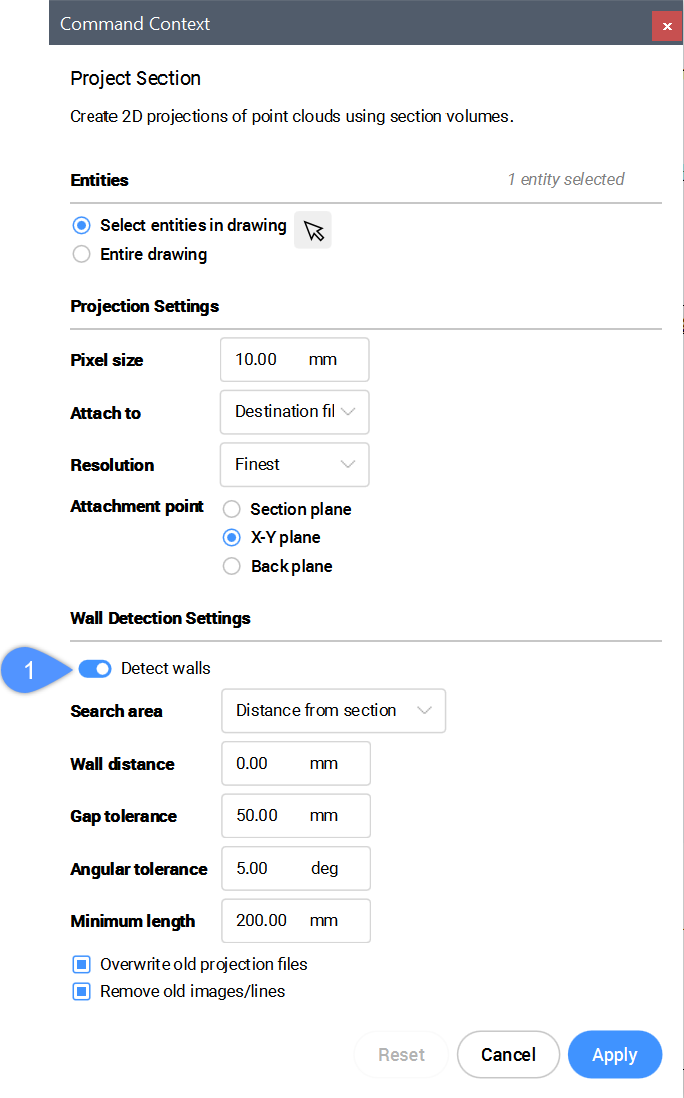
- Click Apply to generate the raster image.Note: If there are some missing lines, you can draw them yourself by tracing the background image.
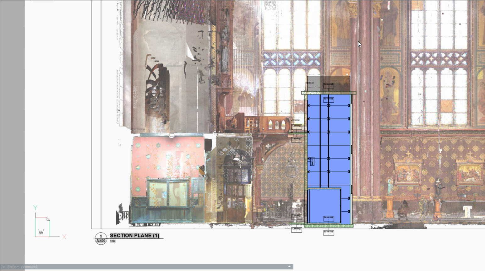
Making vertical sections from point clouds
Make a vertical section box on the location where you want the vertical projection.
Make sure that the blue round arrow aims to the side you want your projection.
Generating BIM sections with point clouds
In some cases it is not necessary to recreate the existing building. Background images can provide more context to the design documents. You can use these images to verify the created 2D geometry and in high quality scans, you can also use them as graphical material. For example, as a background image for a BIM model in renovation projects where modern interventions are made in historical buildings.
Point Cloud scan by Realistic Visual styles.